About Me

My photo
Plastic Moulding Expert :- 1. Thinwall Injection Moulding 2. Extrusion Blow Moulding 3.PET Preform Injection Moulding 4.Single stage Stretch Blow Moulding (ISBM) 5. Injection Blow Moulding (IBM) 6.Expanded Polystyrene (EPS) 7. Multiwall Polycarbonate Sheet Line 8. Solid Polycarbonate Sheet Line

Saturday, July 3, 2021

PET PREFORM

PET PREFORM

After a long time, when I want to start again writing something on Plastics, It took a while to think what should I write, which can helpful for peoples, So decided to share my Practical Experience which I gain working with different organization and different location and while handling different type of machines & molds.

So with this article, I am starting a chain of Plastic molding information which had been gain during my working, The first topic I selected is PET Preform Manufacturing, it is a wide topic involve different different type of Molding technique based on wide rage of Technology available across the world.

PET preform are present in various type, size, shape and Grammage based on End use application.

PET Preform being produced by using different type of PET material, Again Selection of right PET Material is very important, what going to be produce and what is end use of Preform.

So I will cover PET Preform manufacturing based on End use Application start from right PET material selection, Mold, Molding machine and Processing methods.

Thanks to All my friends who likes my post, You All people who are engaged in Plastic Molding manufacturing also can suggest me, What topic can be selected, or if you need more information about.

Thanks.

Sunday, September 4, 2016

The 5 M’s of Molding—Part 5: Method

Once a molding problem has been identified, use “method” to determine whether the issue is with Man, Mold, Machine or Material.

The final M in the 5M equation refers to “Method”. Method is a very broad category that directly applies to man, mold, machine and material. Method also considers all internal and external contributors that affect the key measurable of a lean production operation.

Key measurables in plastic injection consist of production efficiency, scrap and downtime. The primary goal of lean manufacturing is 100% efficiency, 0% scrap and down time that is planned, not unplanned. These goals can sometimes seem to be challenging to achieve, but with proper analysis and approach the end result can be successful and profitable.

As measurables are recorded, a part history is developed. It is this historical data that we use to identify repeating and/or poorly performing variables. It also helps us to scrutinize what areas of production need improvement.

Once clear identification of a problem has been accomplished, it is then time to ask the question, “is this problem directly associated with Man, Mold, Machine or Material?” In some situations, only one of these will require change. In others, it could be all four that need correction. By establishing which of these categories need to be addressed, it becomes easier to develop solutions that will improve our “method”.

Here is an example of the 5 M method in use:

A Japanese headlight manufacturer determined through scrap data that a significant amount of scratches was appearing on parts already assembled. The cost of this sort of rework is quite costly… parts already assembled would need to be tore down, replacement lenses molded and then a second assembly performed to refurbish the part to an acceptable quality level.

man, mold, machine and material were all considered to determine when and how the scratches were occurring. After review of the entire production process from in-mold to assembly, the cause of the scratches was tracked to two separate problems, both of which were directly related to “man”. The problems were:

Parts produced were packed into cardboard for storage. Some scratches were due to operator handling as they were packed. The boxes were stacked on skids and then transported into warehouse racking.

When parts were needed, they were pulled from warehouse and then transported to the assembly area. Some scratches resulted directly from parts jostling as they were handled by warehouse personnel.

To eliminate the problem, special carts were developed made of a soft cloth that allowed for the parts to be packed, stored and transported to assembly without the threat of scratched product from packing and transport. What had been a very large problem became non-existent through proper analysis and methodical approach.

The 5M approach to molding is an excellent way to clearly identify problems, which is the foundation to any problem solving event. Full understanding of any problem helps to develop the most credible solution to the problems presented. Develop, maintain and regularly review recordable data for measuring production, scrap and downtime efficiencies. As the level of historical data increases, factors that improve production are discovered and implemented. That same data also offers insight into what problems exist. Clearly define the problem, and then review whether it is directly related to man, mold, machine or material. Remember that it could be one, several or all four contributing to the situation.


Develop a solid list of all areas contributing to the problem, and then systematically define solutions to those issues. Effective solutions require a complete understanding of the problems being addressed. Utilize all personnel directly related to the problem to best develop understanding and methods for correction. Effectively defining problems and solutions is dependent upon the complete knowledge base of your entire team. As their ability to create and adapt to change is refined, continuous improvement becomes more enjoyable. Clearly defined solutions add to the strength of your organization, bringing it one step closer to world-class manufacturing.

The 5 M’s of Molding—Part 4: Machine

Machinery/Auxiliary Equipment: The molding standard you set is highly dependent upon the machinery and auxiliary equipment you have available to you. Failure to properly assess the capabilities of your equipment will result in a poorly functioning production system. The following components strongly affect a facility’s scrap, downtime and productivity:

1.     Press: Molding machine capabilities are crucial to the design of any manufacturing system. Press tonnage and screw design (such as general purpose vs. nylon) are key factors in process consistency. Match your mold and material to the press to assure that your process control is not limited due to poorly functioning machinery. Also utilize your process data to further assess process control and machine problems.
2.     Robot: Robotics systems are a valuable asset for establishing production and quality systems. When evaluating the production system, always review potential fixes through robot improvements, end of arm tooling or programming changes.
3.     Automation: Other sources of automation should also be reviewed. For instance, if a quality concern keeps repeating itself, look for solutions through automation development. Involve everyone on your production team to fully assess what failures exist within the production system and utilize your engineers to develop working solutions. Better equip your operators and personnel to remove problematic conditions from the production equation.


Preventative maintenance is a key measurable in the Machinery/Equipment category. Unscheduled downtime seriously impedes production efficiencies due to the nature of unexpected system failures and the resulting unprepared approach towards resolution. Scheduled maintenance events are by far the best way to prevent poor performance. Here are some of the areas where preventative maintenance can prevent unscheduled break downs. Each of these components should have their own maintenance log to help establish what concerns are and what frequency of inspection needs to be:

1.     Molding machine: Press breakdowns can be avoided with a regular inspection system in place. Here are some of the primary inspections and a recommended frequency for performing them:
§  Hydraulic Fluid- Quarterly: Fluid samples should be taken and sent to a screener to evaluate metal content and viscosity break down.
§  Hoses- Weekly: Inspect hoses for signs of wear, rubbing or blistering.
§  Screw- Bi-Annually: Remove screw for inspection. Measure flights and shank to determine whether wear is becoming an issue. Also measure the metering zone of the barrel to verify condition.
§  Electrical-Weekly: Look for unsafe conditions and integrity of connectors.
§  Heater Bands- Monthly: Verify that all bands are in working condition


2.     Tooling- It is important to note that a simple 10-minute inspection of every mold per shift can identify problems and prevent hours of down time due to dry slides, pins, etc. Keep detailed records of mold repairs and use them to develop preventative maintenance events and timing. In a short-run shop, simple teardown and cleaning should occur after every run. In cases where molds run for extended periods of time, regular inspection should occur and molds should be torn down and cleaned bi-weekly. In all cases, cleaning frequencies should be developed based on mold history to prevent breakage through intervention and care.

Sunday, August 7, 2016


The 5 M’s of Molding—Part 3: Material


You’ve accounted for variability in two other “Ms”—mold and man—but materials in their lot-to-lot differences and handling challenges pose a distinct threat to repeatability.

Material:  One of the fundamental considerations in processing is the material being used. Processing relies heavily upon the consistency and quality of the plastic that has been chosen for the part’s aesthetic and dimensional make up. Here are some of the primary variables that need to be reviewed during the stages of process development and in some cases continuous improvement.


Properties: Every material has its own unique set of molding properties that must be considered as a molding operation is developed. Here is a list of some of these properties as they relate to part aesthetics and dimensions:

Temperature- Mold and barrel temperatures are a huge part of the molding equation. Some examples of potential heat-related deficiencies would be long cycles, warping, burn at end of fill, gassing, etc.

 Shrinkage- Every material has its own rate of shrinkage and this is one key measurable that should be considered as material choice is being decided.

Melt Flow: Material viscosity is a key component during process development and improvement review. For instance, a heavily ribbed part might be better suited with a material with a low viscosity to assure that the flowfront moves quickly across the ribs preventing an overpack condition.

Aesthetics & Dimension: There are many variations on engineered materials that either benefit or detract from the overall performance and functionality of part production. Utilize the knowledge and resources of your material manufacturer whenever possible to find the appropriate material solutions.

Additives: There are many situations where material additives can create problems or provide solutions. For instance, the use of color mixing may seem cost effective, yet generate scrap due to poor diffusion leading to faulty parts via color swirls. Or from a different perspective, adding a lubricant to polypropylene might eliminate parts sticking in a mold where draft cannot be added. Work with your material supplier to develop and/or improve a part’s molding capabilities.

Drying: Drying is always a major factor in process consistency. Verify that your dryer throughput is sufficient enough to allow adequate time to properly dry the material being used. It is also important to verify that the material is truly dry through moisture analysis.

Characteristics: When choosing a material, it is important to understand what the typical characteristics are regarding a material’s performance and drawbacks. For instance, nylon has a tendency to shrink; polypropylene tends to have sink issues over large or deep ribs. Look for materials that match the functionality of the part being molded while avoiding potential problems associated with material choice.

Sunday, July 10, 2016


The Five “Ms” of Molding—Part II: The Mold


A bad mold can cripple a process; learn what areas should be considered as a tool is evaluated and reviewed.


Tooling is a key foundation block when developing a work program. A poorly designed or improperly functioning mold can become the root cause for systematic failures. In addition, as continuous improvement projects are outlined, the mold should be reviewed for potential improvements through modification. The next section outlines major areas that should be considered as the tool is evaluated and reviewed:

 
Design: The very first step of successful molding is how well the mold has been designed to fit a particular application. Molds that do not perform well because of poor processing capabilities, frequent breakage or fluctuating molding conditions are crippling to a company’s productivity and efficiencies. Molding simulation software is a great tool for mold development. The ability to analyze mold temperature, pressure fluctuation and how the flowfront will likely perform greatly improves the designer’s ability to make adjustments to the tooling to counteract potential molding problems before they happen.


Qualification-Tooling: There are many different aspects to mold qualification. The primary goal of qualifying a mold is to develop tooling that consistently produces quality parts at an optimal cycle time. Here is a list of some of the primary areas that are important to mold qualification.

 
Balancing the runner system: The need to verify that the cavitation is balanced is paramount to a molder’s ability to control his process. Part weights should be consistent and equal. Parts that weigh more or less than the mean should be adjusted by making changes to the gates. Sprue, runners and gates should allow for adequate filling based on material properties.

 
Mold Temperature:  The ability to heat or cool the mold consistently is a vital part of building a consistent process. The mold faces should be checked in multiple areas to verify that temperatures are equal and consistent. Hot or cold spots can cause major inconsistencies. Adding or removing circuits might be needed to accomplish this. In addition, the mold circuitry should be clearly marked to prevent irregular set ups and assure turbulent flow and consistent direction. It is important to measure mold temperature variability in a running state to assure that mold temperature is consistent and not affecting process via hot or cold spots in the mold during molding.

 
Venting: Verify that the mold has adequate venting to meet the needs of the molding application.

 
Validation-Process: Process validation assures that once a process has been developed, the set-up of that process will be repeatable and consistent. Here is a list of some of the primary process controls that should be reviewed to assure that an established process is true and dependable:

 
Melt Temperature: Melt temperature should be verified to be within the recommended temperature window supplied within MSDS data by the material manufacturer.
 

Barrel Temperature: While the process is in a running state, compare actual temperatures to set points. Conditions that allow heats to ride above what the set points dictate create inconsistency in the process.

 
Velocity vs. Fill time: Injection speed should allow room for adjustment as determined by the fill time of a process. If increasing velocity set points does not decrease the fill time, injection speed is maxed out and the potential for process variance increases.

 
Cushion: Cushion should remain consistent to assure that the process is stable.

 
Peak Pressure: Pressure at cut-off should be verified as consistent, and must not be pressure limited by the maximum pressure limit setting. The pressure limit set point should generally be about 200 PSI higher than the peak pressure achieved.

 
Mold & Area Set up: There are a variety of situations where slight or even major set up variations can affect the ability to repeat a process. Here is a list of factors to consider when developing your mold set up plan:

 
Water: It is important to repeat your water set up consistently. Once process has been established, clearly identify supply and return lines to prevent circulation from changing one set to the next. Identify hoses using color and mark circuits

 
Hot Runner: Whenever possible, use the same hot runner box every time you run a mold.
 
Clamp Force: Record and verify that tonnage used stays consistent. Variability in tonnage setpoints can lead to poor venting or flash.

Friday, July 8, 2016

The 5 M’s of Molding—Part I: Man (labor)

The 5 M’s of Molding—Part I: Man (labour)

There are many areas in which personnel affect consistency and repeatability within a plastics operation.


As a plastics operation evolves there are numerous factors affect productivity, and these detractors can be small or large…consistent or sporadic…obvious or hidden. In any continuous improvement-minded facility, there is always a need for repeated analysis of each job being run. The overall success or failure of each individual operation hinges upon effective review of inconsistencies and system failures. The company then develops and implements improvements, approaches and/or corrections to address shortcomings that could potentially include the purchase of specialized tools or equipment to better equip personnel.

One of the key requirements for profitable continuous improvement is starting out with a solid base to build on. When a job is turned over from engineering to production, all facets of the production line need to be in stable working order. This helps to prevent costly down time and scrap directly related to poor set up, and will assure bad product does not reach the customer.

There are 5 key components that must not only be reviewed during engineering’s development of each work system, but also as the job matures through continuous improvement. The “5 M’s of Molding” make up the solid foundation upon which a company develops a successful molding operation. This article outlines these principles and suggests ways to use them for the evolution of a company’s production capabilities.

Man (Labor):
Labor is one of the most critical contributors to the success or failure of any production development. There are many areas in which personnel affect consistency and repeatability within a plastics operation as it evolves. Here are some of the primary points to consider when evaluating labor as an area for improvement:

Work area: Engineering does not end when parts have been removed from the mold. An evaluation must be made as to what steps need to be taken to provide the customer with a top quality part every time. Make sure the area is well lit and mark locations for tables, tools, scrap bin, etc. Area layout should be designed to maximize operator efficiency and great care should be taken to assure that waste-of-motion has been eliminated. Inspection, part preparation and packaging should flow smoothly allowing the operator both comfort and ample inspection time. It is important to remember that the more labor intensive a job becomes, increased quality problems directly related to human error could be the end result.

Tools: As continuous improvement efforts intensify, it is important to listen to the workers who are most involved with the production end. These are the people who day in and day out have their hands on the parts being produced. Listen to their concerns and suggestions for areas of improvement and provide them with the tools that best fits what needs to be accomplished, thoroughly and quickly.

Defects: It is important to note that quality should be molded in and not sorted. There are circumstances though where depending on operators is necessary. Be sure that they have been fully trained regarding what defects they are looking for, and whenever possible show them what area on the part a defect would normally be found. Track scrap data to identify what defects are most common and then look for solutions through mold modification, process change, etc. to eliminate or significantly reduce the defect.

Ergonomics: It is easy to overlook the importance of this category to the overall profitability of a company. Workplace injuries drive insurance costs, which inevitably reduce the overall profitability of every project on the floor. As you are developing work instructions, look for areas of the job that require frequent twisting, bending and turning. Evaluate methods and/or tools to improve the workflow of the station.

Work instructions: Operational instructions are a vitally important tool once the work pattern has been established. Great care should be put into providing all personnel responsible for the various tasks a job requires with very complete and concise directives. Pictures are a great tool that allow visual explanations of various components. Work instructions should be written in the simplest form possible with detailed explanations of all required information.

Human Error: As mistakes happen, review the fault for ways to eliminate failures from happening again. The “5 Why” system is an effective method for getting to the root cause of failures and developing solutions. Here is an example of this method:

Problem: 32 bad pieces were packed that had splay on the parts
 
Why? The operator did not catch the mistake
Why? It was a new defect that had never been seen on this part
Why? The dryer ran low on material which resulted in light splay
Why? The material handler did not check the material as frequently as he should
Why? He is new and needs retraining on the frequency of checking the hopper

Once the 5 why’s have been asked, it is now time to review the problems and establish solutions to prevent a reoccurrence. For instance, the operator missed the mistake because it had never happened before. To fix this we can implement a visual picture or defect part to be kept at the press in order to assure ourselves that the new problem has been passed along to everyone responsible for part inspection. The hopper also ran low due to an inexperienced material handler. The 5 why’s suggests that this person be retrained to prevent this situation from happening again.

Thursday, July 7, 2016

Improve Pinch-off result of multi-layer blow molding

Focus on HDPE PE/EVOH based COEX bottle having drop test failure, Specially in Agrichemical / Pesticide bottles : For reference PA (Polyamide) Material from BASF taken and truly incorporated with new mold design :-

Focusing on PE-HD/Recycled/Tie/PA/ EVOH multi-layer blown molding only. Polyamide here provides good resistance to various chemicals therefore this multi-layer structure is widely used for agro-chemicals e.g. liquid pesticides which contain organic solvents.
[Determination of a “good pinch-off” or a “bad pinch-off” result]
A good pinch-off should to create a welding line which is rather smooth on the outside and forms a flat elevated line or a low bead inside, not a groove.

Extrusion blow molded parts often fail at the parison pinch-off seam of the mold parting line. Common forms of part failure at the pinch-off are cracking from impact, fatigue failure from flexing, or chemical stress cracking. Once the mode of failure is identified, the appropriate processing changes or pinch-off design modifications can be selected to optimize part performance and appearance.
Part failure along the parting line is related to material processing conditions, mold design, or a combination of these factors. Developing the optimal material shape inside the part at the pinch-off is a key to build parting-line integrity.
Selection of polymers


• Ultramid B40L and C40L/C40LX are recommended for multi-layer blow molding containers or bottles, C40L and C40LX provide better dart impact strength therefore suitable for finished product volume bigger than 500ml, while B40L is usually used for no more than 500ml bottles.
• Various tie materials are available in market, but to match low MI and high viscosity PA, strongly suggest to select low MI (no higher than 2.0) MAH-grafted LLDPE based tie material.
• Lower MI HDPE (higher molecular weight) definitely increases the impact strength but anyway its melt viscosity needs to match with polyamide under processing temperature. For example a MI-0.25 is just well matched to Ultramid C40L(X).
Parameters optimization
• Typical temperature profile for Ultramid B40L and C40L(X): 230C/250C/250C for extruder and 195-200C for the die, too low melt temperature of polyamide may cause melt fracture, poor thickness distribution and “bad” grooved pinch-up Weld line.
Mold design
Because of the comparatively high pressure and mechanical stress extered on the mold bottom when (in the closing step) it pinches one end of the parison together, the pinch-off in a nonferrous metal mold is frequently an insert made of hard, tough steel. The effect on the blown part always shows in the so-called weld line.
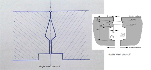
The pinch-off section does not cut off the excess parison tail. Its protruding edges cut nearly through, creating an airtight closure by pinching the parison along a straight line which makes it easy later to break off or otherwise remove the excess tail piece. A high quality pinch-off of a thick-walled parison is more difficult to obtain than that of a thin-walled parison. However, much depends on the construction of the pinch-off insert.


 The pinch-off should not be knife-edged, but, according to some molders, should be formed by lands about 0.1-0.5mm long. The total angle outward from the pinch-off should be acute, up to 15 degree. These two features combine to create a high quality welding line. A groove, which weakens the bottom along the seam, may be formed when these two features of the pinch-off are missing.
One method of obtaining more uniform weld lines is to build “dams” into the mold halves at the parison pin-off areas. These dams force some of the molten resin back into the mold cavities to produce strong, even weld lines.

Tuesday, October 15, 2013

Cooling Channel Design for Mould- Design tips


Cooling Channel Design for Mould- Design tips Moulds are usually built with cooling channels. These channels are usually connected in series with one inlet and one outlet for water flow. The water flow rate may not be enough for turbulent flow because the water pump capacity itself may not be adequate. This obviously leads to random temperature variation on the mould surface. With the result, uncontrolled temperature drift, varying part dimensions and irregular warped surface appears on mouldings. The mould designer should take care of following points: • Thermal conductivity of mould steel influences the rate of heat transfer though mould steel to cooling channel. • Pure Ethylene glycol can be used as Primary fluid transfer medium in closed loop cooling system. Ethylene glycol does not produce rust and mineral deposits in cooling channels. Mixture of water and Ethylene glycol can also be used for circulation through the cooling channel. • Cooling channel diameter should be more for thicker wall thickness: • For wall thickness upto 2mm, channel diameter should be 8 - 10 mm., • For wall thickness upto 4 mm, channel diameter should be 10 - 12 mm., • For wall thickness upto 6 mm, channel diameter should be 10 - 16 mm. • Cooling channels should be as close as possible to the mould cavity / core surfaces. The distance of cooling channel from mould surface should be permissible by the strength of mould steel against possible failure under clamp and injection forces. It could be 1.2 to 2 times diameter of cooling channel. • Cooling system of the mould should have adequate number of cooling channels of suitable size at equal distance from each other and from cavity walls. The center distance between adjacent channel can be 1.7 to 2 times diameter of the channel. This is also governed by the strength of mould steel. • The difference between the inlet and outlet water temperature should be less than 2 to 5 degrees C. However, for precision moulding, it should be 1 degree C or even 0.5 degree C. • Cooling circuits should be positioned symmetrically around the cavity. There can be sufficient number of independent circuits to ensure uniform temperature along the mould surface. • The coolant flow rate should be sufficient to provide turbulent flow in the channel. • There should be no dead ends in the cooling channels. It could provide opportunity for air trap. • Many a times it is difficult to accommodate cooling channels in the smaller cores or cores with difficult geometry. In such case the core should be made of Beryllium copper which has high thermal conductivity. These core inserts should be located near the cooling channel. • The seals of coolant system should not leak inspite of application of frequent clamping force and mould expansion / contraction due to thermal cycle during moulding. The O-ring should be positioned so that there is no chance of them being damaged or improperly seated during mould assembly. Seal and O-ring grove should be machined to closely match the contour of the seal. It should ensure that seal is slightly compressed when the mould is assembled. • Mould temperature above 90 degree C normally requires oil as the heating medium. Heat transfer coefficient of oil is lower than that of water. • There is enough scope for confusion while giving water connection to mould when there are more number of cooling circuits particularly on bigger moulds. A sketch indicating cooling circuits should be available during mould set up. • Hot runner mould should be provided with compression resistant insulating plate between back plate and machine platen. This is to prevent the heat flow from mould to machine platen, which can create an unbalanced heat flow in the mould. With out insulating plate machine platen will act like a big heat sink, there by destabilising the possible balance between heat given to the mould by the hot melt, and heat taken away by circulating water through mould. • The cooling channel layout is suitable when the isothermal i.e. the equi-potential lines, are at a constant distance from surface of the mouldings. This ensures that heat flow density is same everywhere. • Provision for thermocouple fixing should be available at specific one or two places in core as well as cavity to monitor the temperature of mould. • Use efficient sealing methods and materials to eliminate cooling leaks. • Poor mould surface temperature control can cause following quality problems: Axial eccentricity, Radial eccentricity, Angular deviation, Warpage, Surface defects, Flow lines, The mould has to be heated or cooled depending on the temperature outside mould surface and that of environment. If heat loss through the mould faces is more than the heat to be removed from moulding, then mould has to be heated to compensate the excess loss of heat. This heating is only a protection for shielding the cooling area against the outside influence. The heat exchange takes place during cooling time. The design of cooling system has to depend on that section of part, which requires longest cooling time to reach demoulding temperature. Cooling Channel layout depends on : • part geometry, • number of cavities, • ejector and cam systems, • part quality, • dimensional precision, • part surface appearance, • polymer etc. The sizing of cooling channels is dependent on the rate of cooling and temperature control needed for controlling part quality. CAE software like MOLDFLOW or C-Mold can be used to determine the optimised dimension of cooling channel and distance from mould surface, distance between cooling channel, flow rate.

Understanding Mould cooling channel and Cooling system in factory


Understanding Mould cooling channel and Cooling system in factory Introduction Injection moulding process is cyclic in characteristic. Cooling time is about 50 to 75% of the total cycle time. Therefore, optimising cooling time for best performance is very important from quality and productivity point of view. Cooling time is proportional to square of wall thickness. Therefore part design should ensure more or less uniform wall thickness through out the part. Part design should also ensure that the melt flow is uniform in all direction from the gate and melt should reach the boundary of the part more or less at the same time. Cooling channel design - location and size and type - should ensure that melt freezes uniformly inside the mould. Cooling channel design can be perfected with the help of MOLDFLOW analysis. It is necessary to understand Heat Exchange and Cooling Channel design in the mould. Heat Exchange in mould During every injection moulding cycle following heat transfers take place: • from the hot melt to mould steel (heat input to the mould) and • from mould steel to coolant flowing through cooling channel of the mould. (heat removal from the mould) If heat input is more than heat removal, then the mould temperature would keep on increasing from cycle to cycle. Therefore moulding quality would not be constant from cycle to cycle. The moulding quality would be erratic- i.e. varying from cycle to cycle. Therefore, there is a need to balance between the heat input and heat removal in the mould after the desired mould surface temperature is reached. In other words, removal of heat by circulating coolant through the mould cooling channel would arrest the rise of mould temperature above the desired value. In practice, it may not be possible maintain constant mould temperature with respect to time. However, the mould temperature would fluctuate between two values around the desired value. During injection moulding cycle heat flow takes place from polymer melt to mould steel by • effective thermal difusivity of polymer melt and • conduction. This heat is to be removed by circulating cooling fluid through the cooling channels in core as well as cavity during cooling period in order to maintain the desired temperature. Uneven temperature of the mould surface results (uneven shrinkage) in parts with moulded-in stresses, warped sections, sink marks, poor surface appearance and varying part dimensions from cycle to cycle and even cavity to cavity. cont...

Wednesday, October 9, 2013

What are bioplastics? Tear-resistant waste bags for compost


The term “bioplastics” describes two groups of products – “bio-based” and “biodegradable” plastics. Biobased plastics are made either wholly or partly from renewable raw materials and include polylactic acid, polyhydroxyalkanoates, starches, cellulose, chitin and gelatine. Biobased plastics can also be biodegradable – but this is not always the case. Nonbiodegradable biobased materials include biocomposites and composite materials made from wood and plastic. Biodegradable plastic: Special bacteria release enzymes that break down the material’s long polymer chains into small parts that the bacteria subsequently digest and turn into water, carbon dioxide and biomass. To be designated biodegradable in line with the European standard DIN EN 13432, at least 90 percent of the material must have decomposed within 180 days under controlled conditions – high temperature and humidity, and defined oxygen levels. Once these standards are met, the product may display the seedling logo signifying compostability. Biodegradable plastics do not have to be made from renewable raw materials; they can also be petroleum-based. The raw material is unimportant; what matters is the chemical structure of the plastic. When is using bio-based and/or biodegradable plastic a good idea? There are no clear-cut advantages or disadvantages to using fossil-based or renewable raw materials per se. It is best to decide on a case-by-case basis, taking environmental concerns, cost-effectiveness and social impact over the entire product life cycle into account. BASF’s Eco-Efficiency Analysis has shown time and again that bio-based plastics are not always more eco-efficient than their petrochemical-based counterparts. If relatively little water and fertiliser are required, and transportation routes are short, using plant-based raw materials can be best for the environment. But if a large amount of energy is needed to process the materials, this beneficial effect can soon be reversed. Bio-degradable plastics are not necessarily more eco-friendly than other plastics. But for certain applications, they are the best solution – such as mulch films for agriculture, compostable food packaging or shopping bags. The latter have been available at discount supermarket Aldi Süd for the past few years: shoppers can use them a number of times before reusing them at home as compostable bin liners.

Sunday, September 29, 2013

HDPE Bottle for Pesticide and Chemical Industry


Chemical / Pesticide Storage HDPE Bottle : In present condition their is lot of MFg of Plastic HDPE bottle providing the bottle to their customer offering high rigidity by using Marlex or by using the filler to avoid the paneling or deformation problem. As HDPE bottle being produced with normal HDPE material having good ESCR properties which required genuinely to maintain the self life of product having the less rigidity as compare the low ESCR property HDPE grades. But Customer want Bottle for pesticide which can not be easily compressible with hand or want high rigidity to avoid the deformation defects. As per My personnel experience I had overcome on this problem by understanding the customer requirement by providing proper COEX bottle with EVOH or PA barrier layer minimum 70 micron by using GAIL HDPE B52A003 material which have very good ESCR as well as good rigidity as compare to Haldia E5201 and Reliance B56003 HDPE Material. But their is one revolutionary fact came in my knowledge that we can avoid this deformation problem by using Induction wad in which we have ventilation property. These wad had been introduced by MAYER Seals Germany In which they provide such layer configuration which maintain the integrity of product and also provide proper ventilation hole to avoid such vacuum formation which leads to deformation of bottle body. Normally this type of problem had been noticed in 1 ltr Bottle and 500ml Bottle.

Thursday, March 29, 2012

Production of Co-ex EBM Bottles

As per Todays Era Plastic is everywhere and It Helps to replace the Metal in many areas, where it helps to reduce the Weight,

In Extrusion Blow moulding Application Multilayer machine had delivered the Co-ex Bottle for Pesticide Aplication, Agrochemical Aplication, and food Application.

01. Pesticide Bottles :-
- In pesticide Bottles Normally PA (Polyamide) and EVOH (Ethylene-Vinyl alcohol) as a barriar layer in Inner most layer Where chemical come in contact with Bottle Layer.
- Normal Co-ex configuration is 4 layer as below :-
01. "Outer layer" is HDPE Material
02. " 2nd Layer" is Recycle Layer
03. "3rd Layer" is Admer (Adhesive Layer)
04. Inner Layer is PA or EVOH layer
- Providing the Barriar layer in EBM bottles Helps to use those solvant base chemical which is very corrosive in nature and Only being filled in Aluminium Bottles.
- EVOH barriar layer is provide best Oxygen barriar.
- Use of EVOH material as a barriar Layer

Friday, December 16, 2011

Mold Validation Procedure Part-3

Option 4 Description:
This option does not evaluate the inherent material variation. It does investigate the differences attributed to molding the same part in a number of colorants along with the complication of using regrind. The Qualification study requires a representative virgin resin lot of the mean specification. In addition, it requires regrind and adequate amounts of all colorants which will run on the mold.

All the steps during the procedure that involve intimate contact with the blow molding machine are to be done by a qualified injection molding machine operator.

Option 4 Procedure:


Shape of Sample Population for Qualification Study

• Two histograms (6 and 7 classes) indicate that the observations are likely follow a Normal Probability Distribution.
• The 9-class histogram fails the two-question test (see Histogram Construction on page 67) as the population appears to be slightly skewed toward the high end of the distribution.
• Assume that the parent population is indeed normally distributed (represent a more conservative estimate) and proceed with the Capability Analysis (next page).


4.6 Verification (30-Day Run)

Purpose:

The purpose of the Verification study is to determine if the process can sustain key part dimensions within specified tolerances. The Verification consists of monitoring 30 days of production. During this time product quality measures must be met; i.e., Cr, Tz & Cpk.

All the steps during the procedure that involve intimate contact with the blow molding machine are to be done by a qualified blow molding machine operator.
Confirm quality through warehouse checks, trade surveys, and consumer comments.
If all criteria is met during a 30 day time span, the mold is validated.
Procedure:
4.6.1 Begin shipments to the trade, assuring individual component quality using established supplier/plant procedures.
4.6.2 Confirm quality through warehouse checks, trade surveys, and consumer comments.
4.6.3 If all criteria is met during a 30 day time span, the mold is validated.


5.2 CONTROL CHART INTERPRETATION

THREE BASIC RULES

C, P, R


C If any data points are outside the control limits, treat them as a special cause.
Caution: With 3 sigma limits, 3 out of 1000 times will not be a special cause,
but 997 times out of 1000 it will be!


P Since the data should be normally distributed about the mean, look for any non-normal patterns.
The easiest way to do this, is to divide the distance between the UCL and the mean or the LCL and the mean into 3 equal parts or zones.
- If about 68% of the data points fall within the first zone above and below the average, then there are no special causes.
- If there are more than 68% (say 90%) or less than 68% (say 45%) then there are special causes acting on the process.


R If there is a consecutive run of 7 points in a row above or below the mean,
treat the 7 or more points as a special cause, i.e., the process has "shifted".
Think of it as flipping a coin and getting 7 heads in a row.
A very unlikely event!! (Actually, only 8 chances out of 1000!)

5.3 HISTOGRAM CONSTRUCTION


Terms:
N - number of observations.
M - smallest unit of measure.
R - range= high - low.
K - number of classes (square root of N with K_12)
H - class width (R/K).

What:
Histograms are "snap-shot" pictures of a system's output over a defined period of time and shows central location (average), variability (spread), and distribution (shape).


Shape:
To determine if the shape of the histogram is Normal (bell shape curve) as a prerequisite to the capability analysis, answer the following two questions:

1. Does the highest bar of the histogram contain the mean of the sample population?
2. Do the bars on each side of the mean get equally smaller as you move away from the mean?

• If you answer "yes" to both questions, assume a Normal population.
• If you answer "no" to at least one question, determine how non-Normal the population may be, e.g., skewed or truncated. At this point, you may need a computer software capable of performing the capability analysis with a clearly non-Normal population.


5.4 CAPABILITY ANALYSIS COOKBOOK


1. MUST have determined that the Process is stable via Control Charts.
2. MUST have determined that the population is Normal via Histograms of observations.


Thursday, December 15, 2011

Mold Vaildation Procedure Part -2

Mechanical Mold, Head Tooling and In-Mold Labeling Debug
Step 4.2.4:

Verify Process Operation

Purpose:

The purpose of the Verify Process Operation step is to ensure that the mold operates properly after the Mechanical Mold and Select Head Tooling steps have been completed. A slow molding cycle is established (the same rate used in the Parison Centering step) and mold movement should be inspected. At mold operating temperature, verify that the mold opens and closes easily without binding or galling on the leader pins or bushings. The mold ejection and detabing (where applicable) system components should operate smoothly without binding.

With the machine platens in the closed and locked position there should be no gap at the mold parting line. The center of the neck insert (ie, mold position on platen) for most symmetrical containers (without handles) should be aligned under the center line of the die(s). For more complex container designs and containers with handles mold positioning will depend on the blow mold design, type of blow molding process experience through trial and error.

Mold ejection system components should move freely, at normal mold operating temperature, without binding over the full motion range.


Wheel Process Procedure:


Mechanical Mold, Head Tooling and In-Mold Labeling Debug
Step 4.2.5 IML Setup

Purpose:

The IML system must be adjusted to accommodate the mold cavities, label size, and label position on the container. The adjustments must be done in relation to the molds, with the proper placer arm assembly, vacuum cup heads, and label magazines installed.


Procedure for Shuttle Process: (Avery Denison Labeling System)

A. Carriage and Placer Arm Assembly Setup

1. Adjust the carriage and placer arm assembly. Disconnect the actuator links from the front and back sides of the placer arm assembly at the drag links.
2. Check that the angle between actuator arms and the top of the carriage frame is 75 degrees.
3. On the cylinder side only, reconnect the actuator links to the drag link. Check to assure the actuator arm is still in contact with the latch link. Adjust the link as required so that the placer arms are flat against the placer arm bracket and the actuator arm is against the latch link. Adjust the opposite (non cylinder) side, similarly. It is important to ‘balance’ the force on both the front and back side of the actuator links, taking care not to put a
‘jacking force’ on the components.

B. Centering the Placer Arm Assemblies Horizontally Between the Molds

1. Assure adequate daylight opening between mold halves exist on both side A and side B. Back-off the deployment roller (move towards the mold).
2. Move the placer arm assembly between the mold halves to the full in position and set the carriage lock.
3. Loosen the (4) screws that bolt the slide base to the upper frame.
4. Measure the distance from the inside face of the placer arm to the front face of the mold. Repeat the procedure on back face of the mold. If the measurement is not the same turn the adjustment screw located on the upper frame and below the slide base. The placer arm assembly is centered when this distance is the same on both the front and back halves of the mold.
5. Retighten the (4) screws on the slide base.

C. Centering the Vacuum Heads Vertically in the Cavity

1. Back off the deployment roller on the lift-up cam.
2. Move the inserter carriage between the mold halves to the full in position and set the carriage lock.
3. Slightly loosen the (4) screws on the back of the lower frame.
4. Turn the adjustment jackscrew: clockwise to raise, counterclockwise to lower.
5. Check to assure the vacuum cup head is approximately centered vertically in the cavity.
6. Retighten (4) screws.
7. Release the carriage lock and move the carriage out and in by hand to insure that no part of the placer arm interferes with the mold cavities or platen tie rod as it is lifted up into position. Readjust as required, then reset carriage lock to continue.


D. Setting the Tow Bar Length

1. With the placer arm ‘in molds’ and carriage lock engaged, loosen tow bar jam nuts (R.H. and L.H. nuts).
2. While manually extending placer arms, turn the tow bar until vacuum cups are located in the mold cavities as required, usually centered in the label panel area.
3. Tighten the jam nuts.

E. Adjusting the Deployment Roller

1. Assure the carriage lock is engaged.
2. Loosen the lock screw on front of the deployment roller housing.
3. Turn the adjustment screw: clockwise to extend vacuum cups deeper (moves roller away from molds); counterclockwise to retract arms (moves roller towards molds).
4. Check vacuum cup centering, readjust as required.
5. Retighten the lock screw. Placer arm extension should allow for only slight flattening of the vacuum cups against the walls of the mold. Over extension and excessive force may cause excessive wear and premature failure of the placer arm assembly components.

F. Adjusting the Label Magazines

1. Unlock and open the door of the magazine guard.
2. Pull back the pusher plate while holding the remaining stack upright.
3. Load new labels in until desired amount is reached.
4. While releasing pressure on the pusher plate shuffle stack down into and even stack.
5. Close and lock the magazine guard door. Label stacks should be ‘riffled’ several times to eliminate ‘edge welding’ due to die cutting and to allow some air to become entrapped between labels.
6. Set the label stops to allow the labels to be picked easily without double picking or moving the next label out of position. The overlap of the stops onto the label may be different from side to side or top to bottom. The overlap should be about 1/16” initially.
7. Adjust the magazine position (amount of contact force) between the label stack and the vacuum cup heads by moving the magazines in and out. Loosen the lock-down collars and release the lock-down clamp that holds the magazine in place.
8. With the blow molding machine and IML system in ‘Manual’ mode, press the ‘Step/Home’ button to move the first pair of placer arms to the first label pick position. Note how the vacuum cups contact the end label on the stack in the magazine.
9. Adjust the label magazine in or out as required to achieve proper contact. Secure lock-down collars after proper magazine position is achieved.

G. Pick Cylinder Speed

1. Ensure that adequate plant air pressure is available.. Adjust the regulator located on the pneumatic control assembly to 80 psi.
2. Adjust extension speed of the placer arms on valve connected to rod end of cylinder, turn stem: clockwise to slow; counterclockwise to speed up.
3. To adjust retraction speed of the placer arms turn valve connected to other end of cylinder do likewise.

H. Pick and Mold Vacuum

1. The IML system vacuum pumps require 80 psi for optimum performance. Adjust the pick vacuum with the regulator located on the pneumatic control assembly. Settings lower than 60 psi may result in missed picks.
2. Adjust mold vacuum with the regulator located on the pneumatic control assembly. Mold vacuum requirements will vary depending on the number of vacuum ports in the mold, label materials, container shape, etc.

I. Adjusting Label Position on Container

1. The adjustments are side to side, height, and skew (rotation). Adjust the label position by loosening the appropriate clamps and moving the adjustments in direct relation to the container. Retighten clamps to prevent changes in settings due to vibration.

J. Setting Up and Modifying Programs

1. Refer to the IML operating instructions manual for specific program modifications. The number of picks and the position of label picking are normally modified whenever the number of cavities or cavity spacing is changed. No other program modifications are normally required.

4.3 Design of Experiments

A statistical design of experiments, or DOX, is the preferred method to determine an optimum blow molding process and processing window. Initial mold/process evaluations should be completed on a small prototype mold when possible. The mold is normally shipped from the tool builder to the molder's development laboratory. The molder's development laboratory should have the time and resources available to evaluate the molding process for that mold and to perform any initial Design of Experiments.


The objective of a design of experiments is to not only identify an optimum process and processing window, but also to identify the main effects from process variables, interactions between them, and possible curvature effects. Initial experiments are run to determine which combination of process control parameters yields the lowest dimensional variability. Once this is determined, the tool steel can be adjusted to meet the molded container dimensional specifications. It is important NOT to choose process control parameters solely based on the part specifications. If your tool builder constructs the mold using a "Steel Safe" approach, you will be able to easily cut and ‘adjust’ the steel for the most stable and efficient process.

It is recommended that the Design of Experiments be performed on the blow molding machine on which the mold will run on during production or sampling. Only a skilled molding company can accurately translate the process control parameters from one blow molding machine to another. Even if the machines are similar, there are always differences that will affect the attributes of the molded part. The amount of wear on the extruder, the mold clamp system design, hydraulic valves, screw, barrel and timers can differ and can have large effects on process control parameter adjustments. In addition, the molder’s development laboratory often utilizes a different (mold) cooling system than the system used in a manufacturing area. Differences in development laboratory (individual mold temperature control systems) and manufacturing plant (central) coolant system performance can be significant. Careful attention must be given to the actual cooling (heat transfer) variables in the mold.

The following steps are part of the Design of Experiments section:

Step 43.1: Establish Initial Cycle Time

Step 4.3.2: Container Performance Optimization

Step 4.3.3: Commissioning (Multi-Cavity Analysis)

Step 4.3.4: Design of Experiments


Designed Experiments
Step 4.3.1: Establish Initial Cycle Time

Purpose:

The purpose of the Establish Initial Cycle Time step is to begin molding containers for initial dimension measurements, to complete ‘fine’ parison centering adjustments and to increase the rate of extrusion, and the process,
to a typical production level. Extrusion of the parison should be synchronized with the mold shuttle movement or wheel speed (RPM) so that proper pinch-off occurs and the parison is held (using pre-blow or support air as required) in position by the closed mold before blowing. For shuttle blow molding machines the hot knife should cut the parison ‘clean’ without tearing or deforming the parison in the neck area.

Blow molded containers must eject, without sticking in the mold and drop from the mold(s) or strip from the blow pin(s) without ‘hanging-up’.

All the steps during the procedure that involve intimate contact with the blow molding machine are to be done by a qualified blow molding machine operator.
Procedure:


Designed Experiments
Step 4.3.2: Container Performance Optimization

Purpose:

The Container Performance Optimization step is used to establish an initial parsion profile and then to provide a method for adjusting the profile, head tooling ovalization and mold dimensions. Container performance is optimized using an iterative procedure. Optimum container performance is determined by measuring the top load, drop impact, bulge and overflow properties of the containers. As the parison profile and head tooling modifications are developed, molded containers are collected, labeled and conditioned for subsequent dimension measurements and mechanical testing. Sample containers are collected at each parison profile selection and head tooling configuration. All process parameters, head tooling dimensions and container mechanical property data are recorded.
The optimization procedure requires that both mechanical performance data and container dimension data be interpreted before modifying the parison profile and head tooling configuration. Several evaluation iterations are often required to optimize the container performance.

The flowchart on page 39 illustrates the Container Performance Optimization procedure.

Considerations:
Conditioning of the sample containers is recommended (step 4.3.2.9) before performing mechanical tests and measuring dimensions on the containers. However, time constraints on the blow molding machine often need to be considered. When time on the blow molding machine is limited the sample containers are quenched in water immediately after molding and then tested and measured to develop the necessary data for the optimization procedure.

All the steps during the procedure that involve intimate contact with the blow molding machine are to be done by a qualified blow molding machine operator.

Procedure:


Container Performance Optimization


Designed Experiments
Step 4.3.3: Commissioning (Multi-Cavity Analysis)

Purpose:

The purpose of the Commissioning step is to ensure that all mold cavities deliver the same quality, i.e., there is no significant difference of critical cavity dimensions between mold cavities. The time required to perform this analysis is a function of the number of mold cavities and number of critical cavity dimensions. The time on the blow molding machine is minimal compared with the time required to measure the molded containers. However, by performing this analysis the number of containers required to test and measure for future experiments will be reduced significantly.
A solid understanding of creating and interpreting statistical control charts is necessary to perform the multi-cavity analysis.

All the steps during the procedure that involve intimate contact with the blow molding machine are to be done by a qualified blow molding machine operator.
Procedure:


A typical "multi-cavity analysis" curve for the inside diameter of HDPE detergent bottles is shown in Figure 6.

1. The range chart is in control (pass C, P, R1): The variation (range) within any cavity is not significantly different than the mold average-range of 0.0027" (.0068 cm).
2. The average chart fails C (cavities 2, 9, 13): Cavity 2 produces caps that are consistently larger than the rest of the mold cavities while cavities 9 and 13 produce caps that are consistently smaller than the rest of the mold cavities. All other cavities are not significantly different than the average inside diameter of 2.1728" (5.52 cm).

The cause for the "out-of-control" cavities should be investigated and identified. Root causes may be measurement errors, different steel dimensions, unbalanced runner system, small/large gates, different probe tip temperatures, different cooling conditions, etc.


The "multi-cavity analysis" control charts for the injection molded preform of a 32oz.(.946L) bottle is shown
in Figure 7.

1. The range chart is in control (pass C, P, R): The variation (range) in weight within any cavity is not significantly different than the mold average-range of 0.121 grams.
2. The average chart is also in control (pass C, P, R): All weights are not significantly different than the average preform weight of 29.024 grams, i.e., any one cavity is representative of the quality (weight) of the 16 cavity mold.

Since there is no significant weight difference between cavities, on-going monitoring of the weight (as an overall process stability indicator) can be achieved by sampling ONLY one cavity randomly from the 16 cavities in the mold. Remember to spread the observations within samples to capture the "true" process variation.


Designed Experiments
Step 4.3.4: Design of Experiments

Purpose:

The purpose of the Design of Experiments (DOX) is to identify optimum process variables (process control parameters) and the mold(s) processing window. A solid statistical understanding of design of experiments is necessary. There are many different types of software that can be used to assist you in performing design of experiments. Use the design of experiment software that you are most comfortable with.

Design of experiments can require a large amount of time to perform depending on the number of process variables selected to evaluate. In some cases a properly conducted DOX can require 3-4 days to perform, as well as additional time to measure molded container attributes. It is best to perform an extensive design of experiments on a
pre-production mold, i.e., a unit tool, that replicates the production mold(s). This approach normally yields good, reliable results and adequately represents key process variables that effect critical attributes of the molded container.

All the steps during the procedure that involve intimate contact with the blow molding machine are to be done by a qualified blow molding machine operator.

Procedure:


4.4 Qualification (Process Capability Study)

Purpose:

The purpose of the Qualification study is to determine if the process can meet the specified key part tolerance ranges. The first mold being manufactured to produce a molded part might be made “metal safe”. In this case, the Qualification step will determine how much metal needs to be modified in the mold. Resin and colorant properties also need to be evaluated so that process capability may be determined.

Once a process has been selected from performing the DOX, the Qualification study needs to be performed to determine the amount of variation of each key dimension (via control charts). This variation is compared with specified key part tolerances to estimate percent out of specification and product quality measures (Cr, Tz & Cpk). A solid understanding on creating and interpreting statistical control charts is necessary to perform the process capability study.

It is recommended that the Qualification study be performed on the injection molding machine on which the mold will run during production or sampling. Only a skilled molding company can accurately translate the learnings from one injection molding press to another. Even if the machines are similar there are always differences that will affect the attributes of the molded part. The amount of wear to the injection unit, clamping unit, hydraulic valves, screw, barrel and timers can differ and have large effects. In most circumstances the development lab of the molder utilizes a different cooling system than that of a manufacturing area. This is difficult to take into consideration.


Material and Colorant Variation

Resin differences and the addition of colorants effect molded part performance. The rate of the shrinkage changes depending on the resin properties and type of colorant used. This will effect molded part dimensions and mechanical performance. In many cases, there is variation from one resin lot to the next, i.e., lot to lot variation. This lot to lot variation in resin properties is inherent. The resin variation must be evaluated to determine if the material specification range will drive the molded part to be out of the specification. In addition, the Qualification study must properly evaluate each colorant, while including the lot to lot variation in the base resin. Understanding the effects of different colorants is imperative since the same part must be produced in multiple colors from the same mold. The information obtained from the Qualification study results can be used to properly modify the mold.

To quantify base resin, and resin to colorant blend properties, a reliable test method must be selected. Equipment such as the gel permeation chromatograph (GPC), differential scanning calorimeter (DSC) and capillary rheometer are reliable tools for quantifying the lot to lot range. However, it is sometimes difficult to obtain the data from these tools. Material suppliers in all regions generally provide data from the melt flow index (MFI) apparatus. The disadvantage of using the MFI unit is it only provides one data point on the shear rate versus viscosity curve. And, more importantly for qualification purposes, the accuracy of the test is poor. When data from the GPC, DSC or capillary rheometer is not available, regress to the MFI data as a means to quantify the upper, lower, and mean specification of the base resin.

While the mold is being designed, a lot to lot variation representing the maximum expected variation in the resin should be requested from the material supplier. Three lots of the base resin representing the upper, lower and mean specifications from the supplier will deliver an accurate indication of the capability ratio achievable in a production environment. Couple this together with an investigation of all colorants and the percent regrind to capture the remaining sources of inherent variation. Multiple options of the procedure for the Qualification study were created to allow for a variety of different circumstances. A description of when to use each option is provided with the procedure. Review these descriptions to find an option which best meets the needs of your Qualification study.


Option 1 Description:
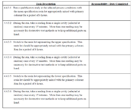
This is the best option to study the inherent material and colorant variation. It requires representative virgin resin lots of the upper, lower and mean specifications. In addition, it requires adequate amounts of all colorants which will run on the mold.

All the steps during the procedure that involve intimate contact with the blow molding machine are to be done by a qualified injection molding machine operator.


Option 2 Description:
This option does not evaluate the inherent material variation. It does investigate the differences attributed to molding the same part in a number of colorants. It requires a representative virgin resin lot of the mean specification. In addition, it requires adequate amounts of all colorants which will run on the mold.

All the steps during the procedure that involve intimate contact with the blow molding machine are to be done by a qualified injection molding machine operator.

Option 2 Procedure:


Option 3 Description:
This option evaluates the inherent material variation along with the complication of using regrind. This Qualification study investigates the variation attributed to molding the same part in a number of colorants. It requires a representative virgin resin lot of the mean specification. In addition, it requires adequate amounts of all colorants which will run on the mold and regrind.

All the steps during the procedure that involve intimate contact with the blow molding machine are to be done by a qualified injection molding machine operator.

Option 3 Procedure:


Continue In Next Post...Thanks