Details of Hai Tai Injection Molding machine:
http://english.china-haitai.com/en-down.php
asses below link for more details. (copy the Link in your Internet browser)
Product Details
http://english.china-haitai.com/prodpics/product.pdf
or
Product
or
http://english.china-haitai.com/prodpics/011013474170.rar
Video of Machine
http://english.china-haitai.com/prodpics/ht.dat
or
About Me

- Ashok Pathak
- Plastic Moulding Expert :- 1. Thinwall Injection Moulding 2. Extrusion Blow Moulding 3.PET Preform Injection Moulding 4.Single stage Stretch Blow Moulding (ISBM) 5. Injection Blow Moulding (IBM) 6.Expanded Polystyrene (EPS) 7. Multiwall Polycarbonate Sheet Line 8. Solid Polycarbonate Sheet Line
Friday, November 27, 2009
Sunday, November 1, 2009
PLASTIC MOLDING TECHNIQUES
Injection Molding Overview : By Ashok Pathak
Injection molding is the most commonly used manufacturing process for the fabrication of plastic parts. A wide variety of products are manufactured using injection molding, which vary greatly in their size, complexity, and application. The injection molding process requires the use of an injection molding machine, raw plastic material, and a mold. The plastic is melted in the injection molding machine and then injected into the mold, where it cools and solidifies into the final part. The steps in this process are described in greater detail in the next section.
Injection molding is used to produce thin-walled plastic parts for a wide variety of applications, one of the most common being plastic housings. Plastic housing is a thin-walled enclosure, often requiring many ribs and bosses on the interior. These housings are used in a variety of products including household appliances, consumer electronics, power tools, and as automotive dashboards. Other common thin-walled products include different types of open containers, such as buckets. Injection molding is also used to produce several everyday items such as toothbrushes or small plastic toys. Many medical devices, including valves and syringes, are manufactured using injection molding as well.
Capabilities
| | Typical | Feasible |
| Shapes: | Thin-walled: Cylindrical
| Flat |
| Part size: | Envelope: 0.01 in³ - 80 ft³
| |
| Materials: | Thermoplastics | Composites
Thermosets |
| Surface finish - Ra: | 4 - 16 μin | 1 - 32 μin |
| Tolerance: | ± 0.008 in. | ± 0.002 in. |
| Max wall thickness: | 0.03 - 0.25 in. | 0.015 - 0.5 in. |
| Quantity: | 10000 - 1000000 | 1000 - 1000000 |
| Lead time: | Months | Weeks |
| Advantages: | Can form complex shapes and fine details Excellent surrface finish
| |
| Disadvantages: | Limited to thin walled parts
| |
| Applications: | Housings, containers, caps, fittings | |
Process Cycle
The process cycle for injection molding is very short, typically between 2 seconds and 2 minutes, and consists of the following four stages:
Clamping - Prior to the injection of the material into the mold, the two halves of the mold must first be securely closed by the clamping unit. Each half of the mold is attached to the injection molding machine and one half is allowed to slide. The hydraulically powered clamping unit pushes the mold halves together and exerts sufficient force to keep the mold securely closed while the material is injected. The time required to close and clamp the mold is dependent upon the machine - larger machines (those with greater clamping forces) will require more time. This time can be estimated from the dry cycle time of the machine.
Injection - The raw plastic material, usually in the form of pellets, is fed into the injection molding machine, and advanced towards the mold by the injection unit. During this process, the material is melted by heat and pressure. The molten plastic is then injected into the mold very quickly and the buildup of pressure packs and holds the material. The amount of material that is injected is referred to as the shot. The injection time is difficult to calculate accurately due to the complex and changing flow of the molten plastic into the mold. However, the injection time can be estimated by the shot volume, injection pressure, and injection power.
Cooling - The molten plastic that is inside the mold begins to cool as soon as it makes contact with the interior mold surfaces. As the plastic cools, it will solidify into the shape of the desired part. However, during cooling some shrinkage of the part may occur. The packing of material in the injection stage allows additional material to flow into the mold and reduce the amount of visible shrinkage. The mold can not be opened until the required cooling time has elapsed. The c ooling time can be estimated from several thermodynamic properties of the plastic and the maximum wall thickness of the part. 
Ejection - After sufficient time has passed, the cooled part may be ejected from the mold by the ejection system, which is attached to the rear half of the mold. When the mold is opened, a mechanism is used to push the part out of the mold. Force must be applied to eject the part because during cooling the part shrinks and adheres to the mold. In order to facilitate the ejection of the part, a mold release agent can be sprayed onto the surfaces of the mold cavity prior to injection of the material. The time that is required to open the mold and eject the part can be estimated from the dry cycle time of the machine and should include time for the part to fall free of the mold. Once t he part is ejected, the mold can be clamped shut for the next shot to be injected.
After the injection molding cycle, some post processing is typically required.
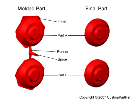
During cooling, the material in the channels of the mold will solidify attached to the part. This excess material, along with any flash that has occurred, must be trimmed from the part, typically by using cutters. For some types of material, such as thermoplastics, the scrap material that results from this trimming can be recycled by being placed into a plastic grinder, also called regrind machines o
granulators, which regrinds the scrap material into pellets. Due to some degradation of the material properties, the regrind must be mixed with raw material in the proper regrind ratio to be reused in the injection molding process.
Equipment
Injection molding machines have many components and are available in different configurations, including a horizontal configuration and a vertical configuration. However, regardless of their design, all injection molding machines utilize a power source, injection unit, mold assembly, and clamping unit to perform the four stages of the process cycle.
Injection unit
The injection unit is responsible for both heating and injecting the material into the mold. The first part of this unit is the hopper, a large container into which the raw plastic is poured. The hopper has an open bottom, which allows the material to feed into the barrel. The barrel contains the mechanism for heating and injecting the material into the mold. This mechanism is usually a ram injector or a reciprocating screw. A ram injector forces the material forward through a heated section with a ram or plunger that is usually hydraulically powere d. Today, the more common technique is t he use of a reciprocating screw. A reciprocating screw moves the material forward by both rotating and sliding axially, being powered by either a hydraulic or electric motor. The material enters the grooves of the screw from the hopper and is advanced towards the mold as the screw rotates. While it is advanced, the material is melted by pressure, friction, and additional heaters that surround the reciprocating screw. The molten plastic is then injected very quickly in
to the mold through the nozzle at the end of the barrel by the buildup of pressure and the forward action of the screw. This increasing pressure allows the material to be packed and forcibly held in the mold. Once the material has solidified inside the mold, the screw can retract and fill with more material for the next shot.
Clamping unit
Prior to the injection of the molten plastic into the mold, the two halves of the mold must first be securely closed by the clamping unit. When the mold is attached to the injection molding machine, each half is fixed to a large plate, called a platen. The front half of the mold, called the mold cavity, is mounted to a stationary platen and aligns with the nozzle of the injection unit. The rear half of the mold, called the mold core, is mounted to a movable platen, which slides along the tie bars. The hydraulically powered clamping motor actuates clamping bars that push the moveable platen towards the stationary platen and exert sufficient force to keep the mold securely closed while the material is injected and subsequently cools. After the required cooling time, the mold is then opened by the clamping motor. An ejection system, which is attached to the rear half of the mold, is actuated by the ejector bar and pushes the solidified part out of the open cavity. 
Injection molding machine - Clamping unit
Machine specifications
Injection molding machines are typically characterized by the tonnage of the clamp force they provide. The required clamp force is determined by the projected area of the parts in the mold and the pressure with which the material is injected. Therefore, a larger part will require a larger clamping force. Also, certain materials that require high injection pressures may require higher tonnage machines. The size of the part must also comply with other machine specifications, such as shot capacity, clamp stroke, minimum mold thickness, and platen size.
Injection molded parts can vary greatly in size and therefore require these measures to cover a very large range. As a result, injection molding machines are designed to each accommodate a small range of this larger spectrum of values. Sample specifications are shown below for three different models (Babyplast, Powerline, and Maxima) of injection molding machine that are manufactured by Cincinnati Milacron.
| | Babyplast | Powerline | Maxima |
| Clamp force (ton) | 6.6 | 330 | 4400 |
| Shot capacity (oz.) | 0.13 - 0.50 | 8 - 34 | 413 - 1054 |
| Clamp stroke (in.) | 4.33 | 23.6 | 133.8 |
| Min. mold thickness (in.) | 1.18 | 7.9 | 31.5 |
| Platen size (in.) | 2.95 x 2.95 | 40.55 x 40.55 | 122.0 x 106.3 |
| | | | |


Subscribe to:
Comments (Atom)