
Ashok Pathak
Pathak2ashok@gmail.com
CMP India
CENTRAL MACHINARRY & PLASTIC PRODUCTS
BLOW MOULDING MACHINE MODEL : 1000/D/H/2
Web site : www.cmppin.com
START UP PROCEDURE
01. Clean the machine thoroughly.
02. Check the connected main cable is of proper rating, ampere with m/c load.
03. Ensure that before startup, the m/c control cabinet (control panels) is well earthed. The earth voltage b/w neutral & ground should be below 1.0volts or machine will shows irregular behavior when you start the AC drive.
04. Clean the hopper and ensure that no foreign material is lying inside the hopper.
05. Start the water supply to hopper cooling block and oil cooler. Also start water supply to mould cooling. Make sure that water temp. does not go below 5 degree to 8 degree at m/c inlet, to ensure a trouble free and fast production rate.
06. Switch on the main isolator which connects supply to control cabinet.
07. Check all three phase of electric are well connected.
08. open the m/c side covers (Hydraulic pump side) operate the hydraulic pump, and check the motor, direction of rotation.
09. Set the various timers as per requirement. Select parison programmed & blowing sequence as per requirements.
10. Start hydraulic operation manually one by one, like mould open, carriage in , blow pin down, blow pin up, carriage out and mould open.
11. Set the mould center with respect to parison tube and set the blow pin center with respect to mould.
12. Start the m/c in fully auto cycle and match the timing with your products.
13. Verify that the cycle is working and all the timers are set properly.
14. Stop auto cycle and keep the m/c function (carriage, bl;ow pin, mold) in its home condition.
15. Switch on barrel heaters, head heaters, clamp heater flange heater & nozzle heaters by switching ON individual switches on the control cabinet. Set the required temp. for individual zones. And hydraulic oil maximum temp.
16. Make sure that the temp. Does not exceed the preset temp. too much. If it shows too much then verify whether the corrected TC is in working condition.
17. Switch on the switch of dimmer stats for nozzle heaters.
18. Allow heating on barrel to continue and check on the screen of the temp. page whether the temp. on each zone is rising. Check periodically heating amperes of each zone for any abnormality.
19. Load the material in the hopper, after closing the shutter slide underneath the hopper.
20. After set temp. Has reached on all the zones allow heat soaking for ½ to 1 hrs. start the extruder fan and increase the extruder speed at low RPM (say 300rpm) i.e. screw speed will be at 20rpm.
21. Open Sutter slide of the hopper to allow a small feed of the material.
22. Material would be plasticized and start oozing out of the die gap. Check for the uniformity of flow through the die gap. If the flow is not uniform adjust the centering screw on the head body for getting uniform flow. Adjust feed of the material if required. Keep the screw speed at minimum value with the help of AC drive and keep close watch of the motor ampere and percentage load.
23. Increase screw RPM steadily, at the same time increase the material feed to the screw by opening the shutter slide of the hopper.
24. Open the air supply main valve, open the air regulator and open hand slide valve as per given below. And check the air pressure in pressure gauge. It should be 7 to 8 bar.

25. Cut the parison by operating the knife. When correct length of parison is extrude, turn the cycle selector switch to auto mode.
26. Now the mould will move towards extruder center, catch the parison and execute the complete cycle.
27. Adjust the various valves for air supply as per requirements.
28. Adjust the extruder speed so that correct length of parison is extruded. Avoid excessive wastage and half shot.
29. Check the blow article. Find out any changes in auto cycle, settings, to achieve optimum production with satisfactory quality.
30. The atmospheric or room temp. Should not exceed 50°C.
Precautions:
01. Earth the m/c and control cabinet before starting up the m/c.
02. Do not fix mould having thickness less than specified.
03. Do not stop the m/c with mould in, and close condition.
04. Ensure the oil strainer for hydraulic tank is not damaged and hydraulic oil is not contaminated.
05. Ensure oil tank covers are firmly fixed in position.’
06. M/c operations should not be continued if hydraulic oil temp. is more than suggested. (preferably 45°C max permissible 55°C)
07. Keep the needle valve closed after checking system pressure.
08. Main extruder motor should not be started with cold material inside the barrel.
Nozzle pin type

Parison weight / wall thickness setting:-

Single head HDPE: in the standard 50ml/200ml/500ml/1000ml/ 2000ml. HDPE head parison tube thickness controlled by rotating the spindle nut in the direction of clock wise or anticlock wise. Both of one direction parison thickness will increase and in the other direction, thickness will decrease. In the diversion nozzle pin the procedure will be opposite from conversion nozzle pin.


Single HDPE head 5 ltr / 10 ltr & 20 ltr. :
In 5 ltr / 10 ltr & 20 ltr HDPE head the process is different from above method. In this m/c you can adjust the weight from spindle nut from bottom or spindle from top or bottom for required nozzle and pin.
Single head PVC: in the PVC head you parison can be controlled with the nozzle pin. You can move the pin up or down both direction and keep the gap between nozzle & pin as per your requirement.
PARISON LENGTH & WEIGHT SETTING IN DOUBLE HEAD :
DOUBLE HEAD DH-60/DH-78/DH98/DH-118 :
if you are facing the problem of parison with unequal length in double head. Then there is a provision of two screw on the both side of the flange by rotating the screw clockwise or anticlock wise you can set the equal length of all parison.
For equal weight setting rotates the spindle nut as per your requirement and controls your product weight.
Note : never full lock the crew situated at the side of flange. It can burst and damage the connected parts near the head or injured the person working near the machine.
PARISON STRAIGHTNESS SETTING :
SINGLE HEAD

DOUBLE HEAD, TRIPLE & FOUR HEAD :

Normal position :
this picture gives the normal profile of the parison under normal condition. Also letters A,B, C, are written to name the bolts and the centre nut to obtain clarity in the setting operations. The can be straight set by the help of A,B&C bolt with the help of Allen key or screw spanner.
When parison will not be in normal condition it will be as follows condition.
PARISON OUT (LEFT OR RIGHT) SIDE FROM CENTER LINE

PARISON MOVING TOWARDS THE IN SIDE OR OUT SIDE (FRONT OR BACK) THE M/C

When parison moves towards the RIGHT as shown in the figure loosen the allen bolts C and tighten the bolts A.
when the parison moves towards the LEFT, loosen the left bolt A and tighten the bolt C.
When parison move backwords, loosen the centre but B and tighten the allen bolts A & C
When the parison moves to forword, loosen the allen bolts A & C and tighten the nut B.
MOULD CENTERING
Setting of left mold: to take the mould towards the right, loosen 1 & 2 equally, and tighten 3 & 4 equally. To take the mold towards the left loosen 3 & 4 and tighten 1 & 2 equally.
Setting the right mold : to take the mold towards the left, loosen the 1 & 2 equally and tighten the 3 & 4 equally. To take the mold towards the right loosen the 3 & 4 equally and tighten the 1 & 2 equally.

Hydraulic pressure setting
BIG PUMP :

• To adjust the pressure, loosen the lock nut & turn the handle knob slowly clockwise for higher pressure or anti clockwise for lower pressures. One revolution of handle make about 50Kgf/cm2 pressure change. After adjustment do not forget to tighten the lock nut.
• To read the pressure, press the pressure Isolator.
• Pressure set in BSG-06-2B3B-D24 with the help of yellow Knob. Pressure in big pump should be 50 to 60Kgf/cm2.
SMALL PUMP :

• Pressure set in the small with the help of MPB-01-H-30 Allen key by loosing the lock nut and setting the pressure with help of 4mm Allen key. After setting the pressure again lock the nut.
• The Allen key to be rotate clock wise to increase the pressure and anticlockwise to decrease the pressure. Pressure in small pump is 100 to 120kgf/cm2.
BLOW PIN SETTING:-
BLOW PIN HEIGHT SETTING :-
The blow pin height can be adjusted by loosing the bolts on the L type bracket fitted on machine bed and shift other L type bracket on which cylinder is fitted up or down as per your requirement and fix it by tighten the bolt at its required position.
The fine adjustment is done by the blow pin stopper assembly at the top of the blowing cylinder in hydraulic cylinder only, rotating the blow pin stopper assembly clock wise will move the blow pin up, and anti clock wise will move the blow pin down. Adjust the blow pin stopper and lock this position with check nut.

Blow pin center setting:-
Blow pin center can be set by loosening the bolt fitted on the machine bed with L type bracket and moving it forward or back position and fix its proper position.
Blowing Hooks setting:
To avoid the mould come down at blowing time adjust the hooks in such way that the Gap b/w two hooks is 0.1 to 0.2mm when mould is in close condition.

PLANNED MAINTENANCE
• The machine should not be operated keeping the safety guards open or any interlocks by passed.
Preventive maintenance:
DAILY :
1. Clean the m/c externally.
2. Lubricate the tie bars and tie rods manually t the start of every shift and hence regularly after three or four hour interval when m/c is in continuous production by means of hand pump.
3. Lubricate all moving parts.
4. Check the oil level of the tank and top up if necessary.
5. Check oil level in the gear box in the oil level indicator.
6. Check oil temp. should not exceed 55C.
7. Check ampere meter (Ammeters) for working of heaters.
8. Check oil level of gear box.
9. Check emergency button, gate safety, proximity switches are working properly.
10. Physically check all important connection on the machine and tighten them if required.
WEEKLY:
1. Check for oil leakage.
2. Check all the loose connections on the machine elements and tighten if required.
3. Remove and clean the suction strainer for hydraulic pump.
4. Check all the safety features provided in the m/c.
5. Contact point of contactors should be checked. If found dirty, clean with carbon tetra chloride.
6. check electrical control cabinet and m/c
7. Check all tie bar nuts, tie rods nuts and rack rods for tightness.
8. Check water circulation in each area.
9. Check and adjust drive belt tension. Adjust it for getting correct tension in belt.
Monthly :
01. Switch on the control; cabinet and keep it in on condition for minimum 20 min. for controller backup battery charging. If machine is not in function for 20 days.
02. Check all hydraulic and pneumatic connection for leakage and rectify whenever necessary.
03. Lubricate all moving parts and greasing where applicable.
04. Check oil level.
05. Clean the suction filter for hydraulic pump. Care should be taken while cleaning the filter not to damages the wire mesh. If damaged, dirt and other foreign particles will be drawn in to pump causing severe damage.
06. Check pressure setting of small and big pump.
07. Replace return line filter cartridge every 1,500 hour if required.
Six monthly:
1. Clean inside the oil cooler, water side and refit it carefully.
2. Empty the hydraulic tank, clean the tank and fill it after filtering and testing its properties.
3. Replace the gear oil with new.
4. Clean the pump cartridge. It should be done by trained engineer.
5. Check hydraulic pump and motor alignment.
6. Check all electrical elements for working condition and connection at every junction.
7. Check loose connection at every joint.
8. Check accumulator pressure in accumulator circuit m/c. if required then refill with nitrogen gas at its required pressure.
Other maintenance:
Oil cooler :
01. Water line must run full size of the oil cooler inlet outlet. Do not reduce the size of the pipe line.
02. Water pressure to maintain minimum 2kg/cm2.
03. Do not use and metal rods to clean the copper tubes. Use nylon brushes to clean the oil cooler.
04. Do not use hard water for oil cooler, this will affect your m/c performance.
05. Clean the heat exchanger every six month with any de-scaling solution. Do not use any acid for cleaning. This will damage the copper tube.
Parison head :
The parison die head is the heart of the blow molding machine, and as such due care should be given in handling the same during operation, dismantling, cleaning or assembly.
The Finish on the edges of the die rings and materials is very important. The original finish on these components should not be damaged.
Any scratches or dent marks of any sort or blemishes appearing on the die ring (core pin), mandrel (nozzle) as well as mandrel holder (core receiver) due to mishandling would result in parison and hence blown articles with scratches, lines etc.
The extruder head cleaning:
• Switch off the power to the heating element you want to disconnect.
• Remove the heater band
• Disconnect the thermocouple.
• Fit an eye bolt in the head connecting the flange.
• Attach a suitable sized cable to the eye bolt.
• Bring the cable under tension using hoisting hook.
• Slacken the nuts which hold the head and extruder together.
• Move the head away from the extruder
• Position it on work bench
Make sure there is power pointy near the bench that can be used to supply the electricity to the head’s heating elements in order to keep the plastic molten.
• Switch on the power to the heating elements to heat them up
• Check that the plastic is in molten state.
• Disconnect the power from the heating elements.
• Disassemble the heating elements.
• Disassemble the head, referring to the drawing supplied.
• Fit the head again.
• Degrease and thoroughly clean all the sliding components.
• Lubricate the threads of all the screws with high temperature grease.
Cleaning the extruder:
Proceed the as follows to clean the extruder correctly:
• Heat the barrel zones, setting the temp. 10-20 deg C higher than the material being processed.
• Switch off the power to the heating elements you want to disconnect
• The head away from the extruder
• Operate the extruder screw at 40 rpm
• Pour a sufficient qty of material for cleaning the cylinder in to the hopper.
• Lower the temp to 100 deg C
• Bring down the screw speed to 30 rpm
• Wait until the cleaning material used comes out of the barrel without any waste matter composed of residues removed from inside the barrel itself.
• Position a suitable container by the extruder out feed for collecting the material extruded from the barrel
• Operate the extruder until the hopper and the barrel are completely empty, if necessary clean out and material left in the hopper using jet of compressed air.
When all the material used for cleaning operation has passed through the extruder, proceed as follows :
• Switch off the screw
• Screw the special extractor tool on to the screw
• Increase the temp. to 10% above the normal work value
• Remove the screw
Place the screw on work bench
You can now proceed to clean the barrel :
• Bring the temp. back to 100 deg C
• Insert a suitable diameter piece and brush out of the barrel
• Blow compressed air filtered inside the barrel
• Use a beam lamp, check that the inside of the barrel is bright throughout
• Slide a piece wrapped in clean rags through the inside to complete the cleaning operations
• Fit the screw back in the spindle without forcing it
• Turn the screw by hand to engage the longitudinal key located at the bottom of the screw in its related grooves in the reduction gear
• Fit the head back on again
• Make sure that the flange thread doesn’t protrude from the head threads
• Grease the threads of the nuts which hold the head on the extruder using high temp grease
• Move the head flange up to the extruder flange. Making sure that they are parallel
• Fit and tighten the nuts
• Gradually increase the head and extruder temp until reaching the production temperature
• Check and if necessary tighten the bolts, tightening them in diagonally opposite pairs


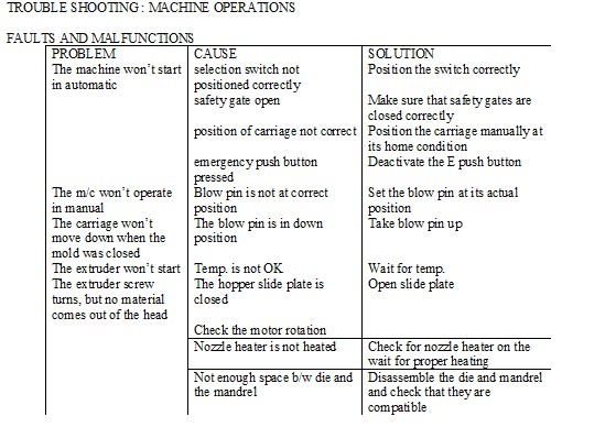
TROUBLE SHOOTING : MACHINE OPERATIONS
FAULTS AND MALFUNCTIONS

SCREEN MIOCROPROCESSOR BL-01 (HP-02)
01. if any temp channel is open or TC is broken then display will show OPEN for that channel. For Ex. Zone2 TC is not connected or broken, then display will show:
Set 1 set 2 Actual
Zone 2 120 002 Open
02. Similarly if there is large variations in input from TC or thermocouple is loose fit causing rapid changes of temp in sensing, display for that channel will show :
Zone3 140 005 Ther. Er.
03. if temperature card is loose or not connected then display will show :
Zone5 160 001 Card Er.
04. If any Temp. Channel is programmed to value 000 then that channel will be out and it will not be read and display for it will show :
Zone1 000 005 OUT
05. In all these cases Output relay will be dienergised to prevent shoot up of temperature and after remedial measure is taken and channel is corrected system will again operating that channel normally.
06. Similarly in case of timers if any timer’s value has been programmed 00.0 then that timer will be out from sequence and its output relay will not be energized.
07. for proper operation of system it is necessary that all the parameters of temp. timers & modes be programmed properly and correctly. So verifiy these parameter in case of any doubt in systems operation and start the system from master RESET.
Faults & remedies :
FAULT 1: No LED display, +5V, -5V, +12V, -12V LED’s OFF.
SOLUTION 1:
(a) Check 24V DC, it should be within +/- 15% maximum.
(b) Check fuse at the front of unit.
(c) Check for burnt wire in power line.
(d) Check 10 way connector from PS card connected to front display unit.
FAULT 2 : As soon as power is switched on fuse below:
SOLUTION 2:
(a) check for short in supply line.
(b) Check fuse rating. It should be 300mA minimum and 500mA maximum.
(c) Check for short between D.C. voltage and OV. This can be checked at supply LED indicator point. All DC voltage and OV is coming there.
(d) Replace P.S. card & check.
FAULT 3 : -5V,+12V,-12V LED’s ON and +5V LED OFF.
SOLUTION 3 :
(a) Check is system is working. If working then there is loose connection in LED’s check LED connection.
(b) Is system not working then check power supply card is properly inserted in bus card.
(c) Check 10 pin flat cable connection between PS card & front & display unit.
(d) Replace PS card & check.
FAULT 4 : +5V ON, but -5V, -12V not coming.
SOLUTION 4 :
(a) check whether A/D card is working, that is temperature coming and relay is energizing properly. If yes then there is loose connection.
(b) If temperature not coming and relay is not energizing then check as per 3b & 3c, & 3d (fault3)
FAULT 5 : PS ON but system is not getting power On page. No display or random Display
SOLUTION 5 :
(a) check system reset key is not pressed or shorted. If shorted or pressed all the display will be blank. Check that reset key connections are not shorting with body. Check green LED on card 1 is blinking. If yes go to step 5C.
(b) check +5V supply is within 4.7V and 5.2V. if not go to solution 3-b, 3-c, 3-d.
(c) press any direct page key.
(d) Check card 1 properly inserted in bus card.
Warning : remove or insert card only after switching OFF power. Donot change card position.
(e) Check display card connector is firmly inserted and no wire is broken.
(f) Check all cards in proper position and fully tight. Firmly but gently set card in guide and insert it into back side connector fully. Check EURO connector pins of any card is not bend. If yes taighten the pins and then insert the card. Always observe correct position while inserting the cards.
(g) Check EURO connect soldering on 1st and 2nd card. If there is any doubt of short b/w two pins, remove it or if any pin is not making proper connection with track, solder it properly. Take care not to spill solder on card or leave air gap on solder. Reconfirm cards insertion is proper & tight.
(h) Remove all other cards except 1st card. Using this card, system can be started and power on page should come.
(i) If with only first card power on page is not coming, then check all IC’s on the card 1 are properly connected to socket. If any socket shows excessive lacker scratch it by knife and clean IC legs by knife.
DO NOT REMOVE IC FROM SOCKET WITHOUT NOTEING ITS POSITION AND POLARITY ON PAPER. IF NECESSARY REMOVE IC ONE BY ONE only and after inserting 1st one, remove second one. WRONG INSERTION WILL DAMAGE THE IC, after removing lacker or rust insert IC into socket gently but firmly. See that all legs are inserted properly and not a single leg is bend or are left out side the socket.
(j) Check that bus card tracks are not short by any piece of connection or solder spills or any wire on bus card is not broken. Check that bottom most and most connections of bus card do not touch the mounting rails. In case of doubt place a insulating tape on mounting rail or insert sleeves in connector pins to isolate it. Check for loose wire or dry solder on bus card connections.
FAULT 6 : power ON page coming but system not working no starting and no Acceptance of key.
SOLUTION 6 :
(a) check that lock is not pressed. If lock LED’s is ON. Then remove lock.
(b) Check if any key is remaining pressed. Under normal working all the keys should be in released conditions. If any key is pressed or shorted, then system will be accept any other key. Put OFF the system and check with multimeter for short on any key. Remove bad key and start the system.
(c) Check if any wire is not broken. Check connection and continuity b/w wires from keyboard and display to KB and display connector on card1.
(d) Check for any short b/w tracks connected to 40pin connector by conducting piece or solder spills on card1. check for any short on 40 pin connector soldered in to card1.
(e) Check for any short b/w tracks by wire, solder spills etc., or key connection tracks in KB and display panel. KB and display section is connected by flat cable. See for short b/w two tracks or cable. Remove shorts if found. Check these with multimeter. Clean the cards with thinner and dry it and then insert and check.
(f) Go to step 5(a) to 5(i)
FAULT 7: system working but certain key is not being accepted by system.
SOLUTION 7:
(a) Check that flat connector for keyboard is firmly and properly inserted into making connector on display card and all the points are making connections.
(b) See that tracks are not broken near connector portion with thinner and dry it.
(c) Check solutions 6-C, 6-d, 6-e
FAULT 8 : Blank display
SOLUTION 8 :
(a) adjust the intensity knob
(b) check the 40pin FRC cable. It should be properly connected to keyboard & CPU card both.
(c) Press and direct page key.
(d) Press master Reset & check.
FAULT 9 : Random display
SOLUTION 9 :
(a) check the 40 PIN FRC cable, it should be properly connected to CPU card 7 key board both.
(b) Press the master reset and then start.
FAULT 10 : temperature showing open in particular Zone.
SOLUTION 10 :
(a) check the thermocouple open.
(b) Check for non connection of TC wire or broken compensating wire.
(c) Short the TC input connection of that channel and see if now temp. shows room temp. if yes then check for broken TC wire, and its connecting compensating wire etc.
(d) Check if ambient temp. in test mode is proper. If not go to solution 15 –a to 15c
(e) Check that TC connection from TC to PCB connector is firm. See the TC wiring diagram
(f) Check the 25 pin connector on card is connected properly or any point of that connector is not broken. Resolder the doubtfull points check the reed relay of particular channels is OK. Check coil resistance of that reed relay. Check IC’s on that cards are properly fitted in to socket. Change the card & check.
(g) Check and replace the card2
FAULT 11 : temperature showing OUT in particular zone
SOLUTION 11 :
(a) check for loose connection in TC
(b) check that TC type is proper and mV is as per standards
(c) go to solution 10-b to 10g
FAULT 12 : Temperature showing –VE in particular zone
SOLUTION 12 : TC is reverse connected. Change the polarity of TC wire.
FAULT 13 : Very rapid variation in temperature.
SOLUTION 13 : check for loose connections, go to solution 10-b to 10-g
FAULT 14 : temperature continuously showing ambient or 0000 in particular zone.
SOLUTION 14 :
(a) heat the Tc. Now temp should increase, if not, then check for short in TC wire or compensating cable or terminal connections. Check all these connections and remove the shorts.
(b) Check that card2 is firmly and properly connected to bus card.
(c) Check all IC’s are properly fitted in to socket
(d) Go to test mode and check the calibration of TC
(e) Go to solution 10-f and 10-g
FAULT 15 : Ambient Temp not showing properly in test mode.
SOLUTION 15 :
(a) if ambient is showing open, then check ambient sensor in temp.card (ADM card)
(b) check the sensor is not touching the body and connection is firm. Replace the sensor and check.
(c) If reading is not proper, then recalibrate the sensor.
(d) If wide variation in reading nd it is not getting calibrated then go solution 15B.
(e) Replace the card & check.
FAULT 16 : all temperature zone showing open OUT, F, 000 or high tem. value
SOLUTION 16 :
(a) check that 25pin connector on ADM card is correctly fitted and its contacts are proper and firm.
(b) Check all IC’s are properly fitted in to socket in ADM card
(c) Check ADM card is properly inserted and is in proper position. Insert the card firmly into bus card if loose.
(d) Check for loose wire or connections on ADM card.
FAULT 17 : particular outputs such as solenoids always ON or OFF
SOLUTION 17 :
(a) go to test mode for Timer and check all outputs. Find out and note down which outputs are always ON or OFF.
(b) Now seee wiring chart for output, it gives details of output type, its connector numbers and card no. for example if DC contactor 2 is always ON, then from wiring diagram it is clear that it is connected to 25 pin connector of card 6. check all wiring continuity from coil of contactor no.2 to card 6 connector. If no continuity then find out the fault and make connection and recheck outputs.
(c) If wiring is OK then check that particular card. Check if fuse is OK. Check transistor is proper. Check for dry solder or broken tracks. Check LED is OK.
(d) Replace card then check. For replacing the card it is necessary that jumper should be properly selected. There are four output cards. Each card has 8 outputs. Card 3 gives first 8 outputs, card 4 gives next. That is from 9th to 16th and so on. Cards can be interchanged by changing jumper. Jumper is having four different positions for card 3,4, 5, and 6. place the cap of jumper where you want to place the card. For example in above mentioned case card 6 is to be replaced.
Now short the jumper marked 6 with jumper cap and then insert this card in 6th card position.
Note : 25 pin connectors are fixed for every position. While cards can be interchanged 6th no connectors should got to 6th position only and so on.
FAULT 18 : PARTICULAR INPUT ALWAYS ON OR OFF.
SOLUTION 18 :
(a) go to test mode for ch. No. and test all input contacts. Find out and note doen input nos. which are always open or close.
(b) Now see wiring chart for input, it gives details of input type, and card no. for example if left mold is always out then proablity LS 11 is always showing open. With help of wiring diagram check continuity from input wire to card connections, if wiring continuity is not there, then make connection and recheck inputs.
(c) Now check that when switch is closed it gives 24V signal (with respect of OV) on that particular wire and when switch is open gives OV. If this is not coming, then check proximity switch and its wiring. If proximity switch and its wiring is proper then +24 V, OV signal on the same wire should come. When switch is pressed and released.
(d) Now check that the card is proper and its 25 pin connector fitted and no two input lines are shot, check for dry solder, loose connection or broken tracks on the card. Check input transistor is ok.
25 PIN CONN.
OUT PUT LED
OUT PUT CARD DIAGRAM
FAULT 19 : no input or no output or both no input and no output.
SOLUTION 19 :
(a) check +24V supply is proper. If not check fuse, rectifier, capacitor and transformer. Check 230V AC to transformer.
(b) Check output and input connector at back is properly connected.
(c) Check output and inputs card are properly fitted and check these cards are getting + 24 V supply.
FAULT 20 : LED coming but solenoid not energizing
SOLUTION 20 :
(a) check output wire going to solenoid is switching to 0 (w.r. to OV) when ON and switching to 24V when OFF.
(b) Put off power and check continuity b/w output wire and solenoid coil.
(c) Check continuity of solenoid coil
(d) Check supply accrose solenoid is proper.
FAULT 21 : solenoid energizing but LED is not coming.
SOLUTION 21 :
(a) check LED’s wire proper
(b) Put off supply check LED’s is proper by multimeter, replace if bad
(c) Check +24V is coming to that LED.
Important : Put OFF supply before removing or inserting cards or before doing any continuity check. Be careful do not short or Mix AC & DC part of supply.
Card arrangement Back
Power supply card
Left 1 2 3 4 5 6 7 8
Card1 : main card
Card2 : temperature card
Card3 to 6: out put cards
Card7 : input cards.
Component on right hand side.
Important notes for timers :
01. open, in, close and out timing should be selected by proper observations. So that machine does not remain idle after completion of particular operation.
02. system delay timing should be selected so that m/c does not remain idle after completion of blowing. If this time is less then blowing timing will be terminated in b/w and if this timing is more then m/c will idle after completion of blowing.
03. by manipulation of delay blow pin and delay blowing timings, pre-blow or post can be achieved. If delay blow pin is less than delay blowing, then blowing will start after blow pin comes down fully. This is called post blowing. On the other hand if delay blow pin is greater than delay blowing, then blowing will start before blow pin comes down. This is called pre blowing.
04. for cutter operation check following timings.
(a) if cutter delay + cutter return delay < delay mould close + delay mould out, then cutter may operate before closure of mold.’
(b) If cutter delay + cutter return delay> delay mould out + mould out, then cutter will not operate at all.
Test mode
To enter Test Mode proceed as follows :-
01. press Master Reset Key.
02. Press 5 no. key
Now test mode page will open up.
03. take the cursor to required line no. such as , Temp, DO (Digital output), DI (digital input) etc.
04. Press key cursor will move to Ch. No. position
05. feed required Ch: No.01,02………etc.
06. press enter
now select Nos. data will be displayed & in acse of digital output selected output will turn on & rest of outputs will be off
07. Repeat step 5 & 6 to check other ch: no. data
08. repeat steps 3 to 6 to check other parameter
09. press master reset to exit from test mode.
Mould memory
01. Master Reset + 7 key.
02. for storing the data bring the cursor on 4th line and press right directional key one time. Now cursor will be under STORE DATA No. feed required mold no. 01 to 30 and press enter one time. Again press right directional key three times and give mold memory name and press enter one time
03. RECALL DATA bring cursor under recall data no. and press mold no. and enter one time then bring cursor under action , press Y key and enter two time.
Un locking : code 0204