
Step 4.2.4:
Verify Process Operation
Purpose:
The purpose of the Verify Process Operation step is to ensure that the mold operates properly after the Mechanical Mold and Select Head Tooling steps have been completed. A slow molding cycle is established (the same rate used in the Parison Centering step) and mold movement should be inspected. At mold operating temperature, verify that the mold opens and closes easily without binding or galling on the leader pins or bushings. The mold ejection and detabing (where applicable) system components should operate smoothly without binding.
With the machine platens in the closed and locked position there should be no gap at the mold parting line. The center of the neck insert (ie, mold position on platen) for most symmetrical containers (without handles) should be aligned under the center line of the die(s). For more complex container designs and containers with handles mold positioning will depend on the blow mold design, type of blow molding process experience through trial and error.
Mold ejection system components should move freely, at normal mold operating temperature, without binding over the full motion range.

Wheel Process Procedure:

Mechanical Mold, Head Tooling and In-Mold Labeling Debug
Step 4.2.5 IML Setup
Purpose:
The IML system must be adjusted to accommodate the mold cavities, label size, and label position on the container. The adjustments must be done in relation to the molds, with the proper placer arm assembly, vacuum cup heads, and label magazines installed.
Procedure for Shuttle Process: (Avery Denison Labeling System)
A. Carriage and Placer Arm Assembly Setup
1. Adjust the carriage and placer arm assembly. Disconnect the actuator links from the front and back sides of the placer arm assembly at the drag links.
2. Check that the angle between actuator arms and the top of the carriage frame is 75 degrees.
3. On the cylinder side only, reconnect the actuator links to the drag link. Check to assure the actuator arm is still in contact with the latch link. Adjust the link as required so that the placer arms are flat against the placer arm bracket and the actuator arm is against the latch link. Adjust the opposite (non cylinder) side, similarly. It is important to ‘balance’ the force on both the front and back side of the actuator links, taking care not to put a
‘jacking force’ on the components.
B. Centering the Placer Arm Assemblies Horizontally Between the Molds
1. Assure adequate daylight opening between mold halves exist on both side A and side B. Back-off the deployment roller (move towards the mold).
2. Move the placer arm assembly between the mold halves to the full in position and set the carriage lock.
3. Loosen the (4) screws that bolt the slide base to the upper frame.
4. Measure the distance from the inside face of the placer arm to the front face of the mold. Repeat the procedure on back face of the mold. If the measurement is not the same turn the adjustment screw located on the upper frame and below the slide base. The placer arm assembly is centered when this distance is the same on both the front and back halves of the mold.
5. Retighten the (4) screws on the slide base.
C. Centering the Vacuum Heads Vertically in the Cavity
1. Back off the deployment roller on the lift-up cam.
2. Move the inserter carriage between the mold halves to the full in position and set the carriage lock.
3. Slightly loosen the (4) screws on the back of the lower frame.
4. Turn the adjustment jackscrew: clockwise to raise, counterclockwise to lower.
5. Check to assure the vacuum cup head is approximately centered vertically in the cavity.
6. Retighten (4) screws.
7. Release the carriage lock and move the carriage out and in by hand to insure that no part of the placer arm interferes with the mold cavities or platen tie rod as it is lifted up into position. Readjust as required, then reset carriage lock to continue.
D. Setting the Tow Bar Length
1. With the placer arm ‘in molds’ and carriage lock engaged, loosen tow bar jam nuts (R.H. and L.H. nuts).
2. While manually extending placer arms, turn the tow bar until vacuum cups are located in the mold cavities as required, usually centered in the label panel area.
3. Tighten the jam nuts.
E. Adjusting the Deployment Roller
1. Assure the carriage lock is engaged.
2. Loosen the lock screw on front of the deployment roller housing.
3. Turn the adjustment screw: clockwise to extend vacuum cups deeper (moves roller away from molds); counterclockwise to retract arms (moves roller towards molds).
4. Check vacuum cup centering, readjust as required.
5. Retighten the lock screw. Placer arm extension should allow for only slight flattening of the vacuum cups against the walls of the mold. Over extension and excessive force may cause excessive wear and premature failure of the placer arm assembly components.
F. Adjusting the Label Magazines
1. Unlock and open the door of the magazine guard.
2. Pull back the pusher plate while holding the remaining stack upright.
3. Load new labels in until desired amount is reached.
4. While releasing pressure on the pusher plate shuffle stack down into and even stack.
5. Close and lock the magazine guard door. Label stacks should be ‘riffled’ several times to eliminate ‘edge welding’ due to die cutting and to allow some air to become entrapped between labels.
6. Set the label stops to allow the labels to be picked easily without double picking or moving the next label out of position. The overlap of the stops onto the label may be different from side to side or top to bottom. The overlap should be about 1/16” initially.
7. Adjust the magazine position (amount of contact force) between the label stack and the vacuum cup heads by moving the magazines in and out. Loosen the lock-down collars and release the lock-down clamp that holds the magazine in place.
8. With the blow molding machine and IML system in ‘Manual’ mode, press the ‘Step/Home’ button to move the first pair of placer arms to the first label pick position. Note how the vacuum cups contact the end label on the stack in the magazine.
9. Adjust the label magazine in or out as required to achieve proper contact. Secure lock-down collars after proper magazine position is achieved.
G. Pick Cylinder Speed
1. Ensure that adequate plant air pressure is available.. Adjust the regulator located on the pneumatic control assembly to 80 psi.
2. Adjust extension speed of the placer arms on valve connected to rod end of cylinder, turn stem: clockwise to slow; counterclockwise to speed up.
3. To adjust retraction speed of the placer arms turn valve connected to other end of cylinder do likewise.
H. Pick and Mold Vacuum
1. The IML system vacuum pumps require 80 psi for optimum performance. Adjust the pick vacuum with the regulator located on the pneumatic control assembly. Settings lower than 60 psi may result in missed picks.
2. Adjust mold vacuum with the regulator located on the pneumatic control assembly. Mold vacuum requirements will vary depending on the number of vacuum ports in the mold, label materials, container shape, etc.
I. Adjusting Label Position on Container
1. The adjustments are side to side, height, and skew (rotation). Adjust the label position by loosening the appropriate clamps and moving the adjustments in direct relation to the container. Retighten clamps to prevent changes in settings due to vibration.
J. Setting Up and Modifying Programs
1. Refer to the IML operating instructions manual for specific program modifications. The number of picks and the position of label picking are normally modified whenever the number of cavities or cavity spacing is changed. No other program modifications are normally required.
4.3 Design of Experiments
A statistical design of experiments, or DOX, is the preferred method to determine an optimum blow molding process and processing window. Initial mold/process evaluations should be completed on a small prototype mold when possible. The mold is normally shipped from the tool builder to the molder's development laboratory. The molder's development laboratory should have the time and resources available to evaluate the molding process for that mold and to perform any initial Design of Experiments.
The objective of a design of experiments is to not only identify an optimum process and processing window, but also to identify the main effects from process variables, interactions between them, and possible curvature effects. Initial experiments are run to determine which combination of process control parameters yields the lowest dimensional variability. Once this is determined, the tool steel can be adjusted to meet the molded container dimensional specifications. It is important NOT to choose process control parameters solely based on the part specifications. If your tool builder constructs the mold using a "Steel Safe" approach, you will be able to easily cut and ‘adjust’ the steel for the most stable and efficient process.
It is recommended that the Design of Experiments be performed on the blow molding machine on which the mold will run on during production or sampling. Only a skilled molding company can accurately translate the process control parameters from one blow molding machine to another. Even if the machines are similar, there are always differences that will affect the attributes of the molded part. The amount of wear on the extruder, the mold clamp system design, hydraulic valves, screw, barrel and timers can differ and can have large effects on process control parameter adjustments. In addition, the molder’s development laboratory often utilizes a different (mold) cooling system than the system used in a manufacturing area. Differences in development laboratory (individual mold temperature control systems) and manufacturing plant (central) coolant system performance can be significant. Careful attention must be given to the actual cooling (heat transfer) variables in the mold.
The following steps are part of the Design of Experiments section:
Step 43.1: Establish Initial Cycle Time
Step 4.3.2: Container Performance Optimization
Step 4.3.3: Commissioning (Multi-Cavity Analysis)
Step 4.3.4: Design of Experiments
Designed Experiments
Step 4.3.1: Establish Initial Cycle Time
Purpose:
The purpose of the Establish Initial Cycle Time step is to begin molding containers for initial dimension measurements, to complete ‘fine’ parison centering adjustments and to increase the rate of extrusion, and the process,
to a typical production level. Extrusion of the parison should be synchronized with the mold shuttle movement or wheel speed (RPM) so that proper pinch-off occurs and the parison is held (using pre-blow or support air as required) in position by the closed mold before blowing. For shuttle blow molding machines the hot knife should cut the parison ‘clean’ without tearing or deforming the parison in the neck area.
Blow molded containers must eject, without sticking in the mold and drop from the mold(s) or strip from the blow pin(s) without ‘hanging-up’.
All the steps during the procedure that involve intimate contact with the blow molding machine are to be done by a qualified blow molding machine operator.
Procedure:

Designed Experiments
Step 4.3.2: Container Performance Optimization
Purpose:
The Container Performance Optimization step is used to establish an initial parsion profile and then to provide a method for adjusting the profile, head tooling ovalization and mold dimensions. Container performance is optimized using an iterative procedure. Optimum container performance is determined by measuring the top load, drop impact, bulge and overflow properties of the containers. As the parison profile and head tooling modifications are developed, molded containers are collected, labeled and conditioned for subsequent dimension measurements and mechanical testing. Sample containers are collected at each parison profile selection and head tooling configuration. All process parameters, head tooling dimensions and container mechanical property data are recorded.
The optimization procedure requires that both mechanical performance data and container dimension data be interpreted before modifying the parison profile and head tooling configuration. Several evaluation iterations are often required to optimize the container performance.
The flowchart on page 39 illustrates the Container Performance Optimization procedure.
Considerations:
Conditioning of the sample containers is recommended (step 4.3.2.9) before performing mechanical tests and measuring dimensions on the containers. However, time constraints on the blow molding machine often need to be considered. When time on the blow molding machine is limited the sample containers are quenched in water immediately after molding and then tested and measured to develop the necessary data for the optimization procedure.
All the steps during the procedure that involve intimate contact with the blow molding machine are to be done by a qualified blow molding machine operator.
Procedure:


Container Performance Optimization


Designed Experiments
Step 4.3.3: Commissioning (Multi-Cavity Analysis)
Purpose:
The purpose of the Commissioning step is to ensure that all mold cavities deliver the same quality, i.e., there is no significant difference of critical cavity dimensions between mold cavities. The time required to perform this analysis is a function of the number of mold cavities and number of critical cavity dimensions. The time on the blow molding machine is minimal compared with the time required to measure the molded containers. However, by performing this analysis the number of containers required to test and measure for future experiments will be reduced significantly.
A solid understanding of creating and interpreting statistical control charts is necessary to perform the multi-cavity analysis.
All the steps during the procedure that involve intimate contact with the blow molding machine are to be done by a qualified blow molding machine operator.
Procedure:

A typical "multi-cavity analysis" curve for the inside diameter of HDPE detergent bottles is shown in Figure 6.
1. The range chart is in control (pass C, P, R1): The variation (range) within any cavity is not significantly different than the mold average-range of 0.0027" (.0068 cm).
2. The average chart fails C (cavities 2, 9, 13): Cavity 2 produces caps that are consistently larger than the rest of the mold cavities while cavities 9 and 13 produce caps that are consistently smaller than the rest of the mold cavities. All other cavities are not significantly different than the average inside diameter of 2.1728" (5.52 cm).
The cause for the "out-of-control" cavities should be investigated and identified. Root causes may be measurement errors, different steel dimensions, unbalanced runner system, small/large gates, different probe tip temperatures, different cooling conditions, etc.

The "multi-cavity analysis" control charts for the injection molded preform of a 32oz.(.946L) bottle is shown
in Figure 7.
1. The range chart is in control (pass C, P, R): The variation (range) in weight within any cavity is not significantly different than the mold average-range of 0.121 grams.
2. The average chart is also in control (pass C, P, R): All weights are not significantly different than the average preform weight of 29.024 grams, i.e., any one cavity is representative of the quality (weight) of the 16 cavity mold.
Since there is no significant weight difference between cavities, on-going monitoring of the weight (as an overall process stability indicator) can be achieved by sampling ONLY one cavity randomly from the 16 cavities in the mold. Remember to spread the observations within samples to capture the "true" process variation.

Designed Experiments
Step 4.3.4: Design of Experiments
Purpose:
The purpose of the Design of Experiments (DOX) is to identify optimum process variables (process control parameters) and the mold(s) processing window. A solid statistical understanding of design of experiments is necessary. There are many different types of software that can be used to assist you in performing design of experiments. Use the design of experiment software that you are most comfortable with.
Design of experiments can require a large amount of time to perform depending on the number of process variables selected to evaluate. In some cases a properly conducted DOX can require 3-4 days to perform, as well as additional time to measure molded container attributes. It is best to perform an extensive design of experiments on a
pre-production mold, i.e., a unit tool, that replicates the production mold(s). This approach normally yields good, reliable results and adequately represents key process variables that effect critical attributes of the molded container.
All the steps during the procedure that involve intimate contact with the blow molding machine are to be done by a qualified blow molding machine operator.
Procedure:


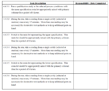
4.4 Qualification (Process Capability Study)
Purpose:
The purpose of the Qualification study is to determine if the process can meet the specified key part tolerance ranges. The first mold being manufactured to produce a molded part might be made “metal safe”. In this case, the Qualification step will determine how much metal needs to be modified in the mold. Resin and colorant properties also need to be evaluated so that process capability may be determined.
Once a process has been selected from performing the DOX, the Qualification study needs to be performed to determine the amount of variation of each key dimension (via control charts). This variation is compared with specified key part tolerances to estimate percent out of specification and product quality measures (Cr, Tz & Cpk). A solid understanding on creating and interpreting statistical control charts is necessary to perform the process capability study.
It is recommended that the Qualification study be performed on the injection molding machine on which the mold will run during production or sampling. Only a skilled molding company can accurately translate the learnings from one injection molding press to another. Even if the machines are similar there are always differences that will affect the attributes of the molded part. The amount of wear to the injection unit, clamping unit, hydraulic valves, screw, barrel and timers can differ and have large effects. In most circumstances the development lab of the molder utilizes a different cooling system than that of a manufacturing area. This is difficult to take into consideration.
Material and Colorant Variation
Resin differences and the addition of colorants effect molded part performance. The rate of the shrinkage changes depending on the resin properties and type of colorant used. This will effect molded part dimensions and mechanical performance. In many cases, there is variation from one resin lot to the next, i.e., lot to lot variation. This lot to lot variation in resin properties is inherent. The resin variation must be evaluated to determine if the material specification range will drive the molded part to be out of the specification. In addition, the Qualification study must properly evaluate each colorant, while including the lot to lot variation in the base resin. Understanding the effects of different colorants is imperative since the same part must be produced in multiple colors from the same mold. The information obtained from the Qualification study results can be used to properly modify the mold.
To quantify base resin, and resin to colorant blend properties, a reliable test method must be selected. Equipment such as the gel permeation chromatograph (GPC), differential scanning calorimeter (DSC) and capillary rheometer are reliable tools for quantifying the lot to lot range. However, it is sometimes difficult to obtain the data from these tools. Material suppliers in all regions generally provide data from the melt flow index (MFI) apparatus. The disadvantage of using the MFI unit is it only provides one data point on the shear rate versus viscosity curve. And, more importantly for qualification purposes, the accuracy of the test is poor. When data from the GPC, DSC or capillary rheometer is not available, regress to the MFI data as a means to quantify the upper, lower, and mean specification of the base resin.
While the mold is being designed, a lot to lot variation representing the maximum expected variation in the resin should be requested from the material supplier. Three lots of the base resin representing the upper, lower and mean specifications from the supplier will deliver an accurate indication of the capability ratio achievable in a production environment. Couple this together with an investigation of all colorants and the percent regrind to capture the remaining sources of inherent variation. Multiple options of the procedure for the Qualification study were created to allow for a variety of different circumstances. A description of when to use each option is provided with the procedure. Review these descriptions to find an option which best meets the needs of your Qualification study.
Option 1 Description:
This is the best option to study the inherent material and colorant variation. It requires representative virgin resin lots of the upper, lower and mean specifications. In addition, it requires adequate amounts of all colorants which will run on the mold.
All the steps during the procedure that involve intimate contact with the blow molding machine are to be done by a qualified injection molding machine operator.


Option 2 Description:
This option does not evaluate the inherent material variation. It does investigate the differences attributed to molding the same part in a number of colorants. It requires a representative virgin resin lot of the mean specification. In addition, it requires adequate amounts of all colorants which will run on the mold.
All the steps during the procedure that involve intimate contact with the blow molding machine are to be done by a qualified injection molding machine operator.
Option 2 Procedure:


Option 3 Description:
This option evaluates the inherent material variation along with the complication of using regrind. This Qualification study investigates the variation attributed to molding the same part in a number of colorants. It requires a representative virgin resin lot of the mean specification. In addition, it requires adequate amounts of all colorants which will run on the mold and regrind.
All the steps during the procedure that involve intimate contact with the blow molding machine are to be done by a qualified injection molding machine operator.
Option 3 Procedure:

Continue In Next Post...Thanks
I am truly dazzled with your blog article, such incredible and helpful learning you referenced here.Your post is extremely enlightening. I have perused every one of your posts and all are useful. Much obliged for sharing and keep it up this way.
ReplyDeletePlastic Mold Manufacturer | China Mold Manufacturer
Thank you for this wonderful info
ReplyDeletei have one question related to step 4.3.3 I made R chart for my product that have 32 cavity the thing is more than cavity is out of UCL(16.86179) and LCL (16.84782) put in relation with USL(17.40) and LSL(16.38) there is huge difference, so i think there is no significant difference between the cavities that will require me to do CAP but how can i reflect this in my report in order to continue validation
I really like your post. Thanks for sharing such a informative blog. Keep posting and upgrading our knowledge.
ReplyDeleteBottle Neck Cutter
Hi..
ReplyDeleteI appreciate your informative post and thanks for sharing.
Bottle Neck Cutter Machine